Eng-Tips is the largest engineering community on the Internet

Intelligent Work Forums for Engineering Professionals

Revolve Elements in Simcenter Femap

Status
Not open for further replies.

Ian_1066

New member
Mar 21, 2024
5
0
0
GB
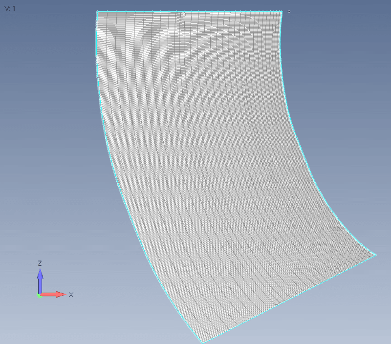
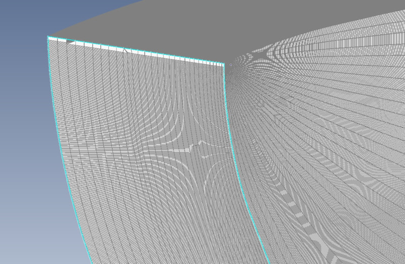
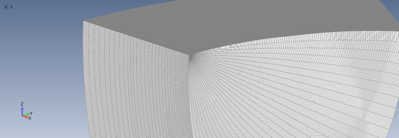
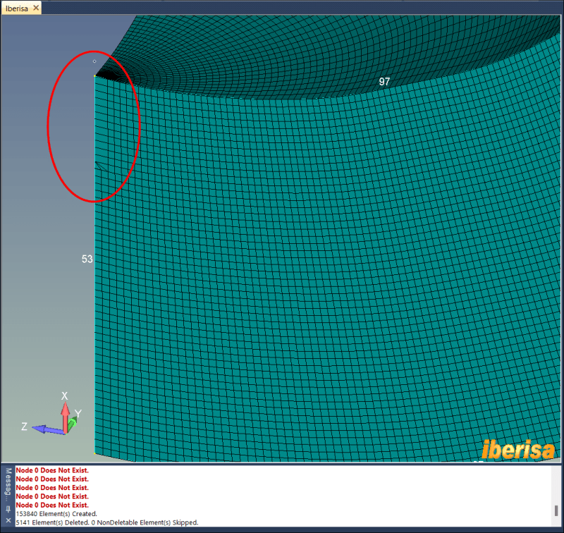
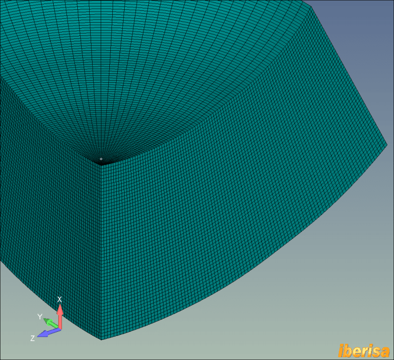
I have been trying to create a body of revolution in FEMAP but I am having issues with small cells when it is near the axis of revolution. This is shown in the attached figure where the top rows of element are somehow merged. Does anyone have a good solution for this or know why it is happening?

As further information, I know the elements wouldn't be great for structural modelling, but I am intending to use the mesh for aerodynamics.

Thanks
Ian

revolve_x9pgah.png
 
Replies continue below

Recommended for you

Do you use Mesh->Revolve->Element command? Can you attach Femap model or neurtal file with your mesh because i can not recreate your error?
 
Yes I am using the Mesh -> Revolve -> Element command.

It is very strange as if I only export the region where I am having the issues as a .neu file and then read it in, the revolve works but if I export the whole model it doesn't. When I run the revolve command is says "Node 0 Does Not Exist" lots of times as a warning message.

The modfem with the error is attached.
 
 https://files.engineering.com/getfile.aspx?folder=6c620ae5-4d32-4bce-b329-4ceafa3e9539&file=revolve.modfem
It is also interesting that I exported just the mesh as a Nastran bdf, reimported it and did the same rotation and it still produces the same error.

I'm not sure if it is a scaling issue as the total model is 30m but the smallest element is 1mm.
 
Yes, now I can recreate error on your model. Interesting. Maybe problem in scaling. Measure distance in model, whole your part is like 0.1x0.1 units, not 30 m as you say. Maybe roundoff errors on such small scale chew up your mesh.
Try to create new model. On empty model before any geometry import/creation go to File->Preferences->Geometry/Model and set scale factor to meters.
Create or import geometry. If you import geometry that immediately after import use measure tool and check size of your model, if it is wrong than repeat import with different scale coefficient, calculate it based on known dimensions of model. Do not scale wrong imported geometry, delete it and repeat import.

Image_001_f9fq6o.png
 
Thanks for your input. Your workaround doesn't work as I am generating the geometry in FEMAP anyway and am only importing some points as a csv file. The geometry is all in metres from the start.

It seems to be definitely related to the dimensions as if I delete the farfield surface and all the mesh then rebuild, the issue doesn't occur. However when I reintroduce the far field I am now getting an issue on the farfield to nearfield boundary. It's one of those things that should take 30 minutes and ends up taking 3days!
 
Dear Ian,
I guess this is a problem related with model dimmensions or internal tolerances, without the <FULL> FEMAP model in hand is not possible to say more, but check the following:
• I strongly suggest to work always in millimeters to avoid meshing problems related with tolerances: is something hard-coded internally in the mesher, when meshing in meters with element size = 1 mm is 1/1000 = 0.001 meters, and this could cause a problem with the tolerances used internally by the mesher.
When I open your FEMAP model I see the following warning message: this means that your model is using different geometry scale factor than me, I run millimeters.
Code:
Geometry Scale Factors are inconsistent with current model.
Attempting to adjust inconsistent Geometry Scale Factors.

• Second: check if the model is outside of the Parasolid BOX, if yes you will have problems like the one reported.

Parasolid-geometry-kernel_uyjd24.png


Parasolid-geometry-scale-factor_asihk0.png


Best regards,
Blas.

~~~~~~~~~~~~~~~~~~~~~~
Blas Molero Hidalgo
Ingeniero Industrial
Director

IBERISA
48004 BILBAO (SPAIN)
WEB: Blog de FEMAP & NX Nastran:
 
Ian_1066
I don't know if this helps i any way but I opened the file "revolve" in Femap 2401 and the geometry looks different compared to the your figures.
As info, I always work in meters.

Capture1_pbsh76.png
 
Hi Thomas and Blas,

Thank you for your inputs.

@Thomas the bit that I show in the figures is just the top of this panel plus I have deleted the panel behind it. If you try revolving the mesh around to (0 0 0) to (1 0 0) vector by 90 degree with 30 elements around the sweep length you should see the same issue where the mesh near the axis distorts itself.
Untitled_avz591.jpg


@Blas. I think you are correct that it is a numerical issue with the rounding. I tried deleting the geometry and repeating the revolving process as described above and it seems to be fine
Untitled2_z52vhx.jpg


I will try removing all the geometry from the full model and see if this same process works okay.

Ian
 
Dear Ian,
I got it!!.
In fact, if I delete ALL POINTS the mesher runs OK.
I will explain: In the model if you do a ZOOM OUT you will see points in the screen, separated by a distance around 12000 mm.
This is the problem: as told, the FEMAP mesher takes in consideration the MERGE TOLERANCE, a value computed automatically when you import the CAD geometry.

STEPS TO REPLICATE THE PROBLEM
• I convert the model from meters to mm using TOOLS > CONVERT UNITS > LOAD > IDEAS_from_m_N_degK_to_mm_N_degC.CF
• Next I issue command TOOLS > PARAMETERS. You can see the value of merge tolerance = 1.6 mm, critical!!.

MERGE-TOLERANCE2_vurecj.png


I delete your 2-D mesh, and apply to the surface the mapped-four corner meshing approach, with eleent size = 2 mm (remember the merging tolerance value) and mesh the surface with PLOT PLANAR elements.

revolve-mesh1_rdtfw3.png


>>Remember: the free EXTRA points are not deleted yet.<<

If I perform the MESH > REVOLVE > ELEMENT command following your indications I get the following result:

revolve-mesh2_ilwtnz.png


Next, I will UNDO the REVOLVE command and DELETE ALL EXTRA POINTS (10 points deleted).
If I issue the TOOLS > PARAMETERS command I will see the following: merge tolerance is recomputed and the new value = 0.0236 mm

revolve-mesh3_lrq0b6.png


If I repeat the MESH > REVOLVE > ELEMENT command the result is the following: the generated mesh is perfect!!. Not any warning issued of "Node 0 does not exist", all is perfect.

revolve-mesh4_c99pun.png


In summary: the model dimmension is important, if affect the merging tolerance, a key fator for both meshing task and geometry operations when performing intersections between surfaces or boolean operations with solids, OK?. Alwys take a look to TOOLS > PARAMETERS command, remove extra geometry that coul affect the performance of the FEMAP model.
Enjoy!!, and work always in millimeters, forgot meters.
Best regards,
Blas.

~~~~~~~~~~~~~~~~~~~~~~
Blas Molero Hidalgo
Ingeniero Industrial
Director

IBERISA
48004 BILBAO (SPAIN)
WEB: Blog de FEMAP & NX Nastran:
 
Status
Not open for further replies.
Back
Top