Continue to Site

Eng-Tips is the largest engineering community on the Internet

Intelligent Work Forums for Engineering Professionals

  • Congratulations MintJulep on being selected by the Eng-Tips community for having the most helpful posts in the forums last week. Way to Go!

Rewinding a Motor from 50Hz to 60Hz 5

Status
Not open for further replies.

Richard888

Automotive
Nov 19, 2012
9
Hi guys I'm new here and in need of your professional advice.

I have a burnt Karcher HD 6/15C pressure washer. The motor was a 230Vac single phase 50Hz 3.1kw we connect it to 230Vac 60Hz and the windings get burnt.

Now I'd like to rewind it and I've been searching the net on how to convert it to same voltage but at 60Hz.

Do I need to increase the turns by 60/50 and reduce the wire size by 50/60 in circular mils for me to convert it from 50Hz to 60Hz motor? and also do I need to change the capacitor value?

Thanks

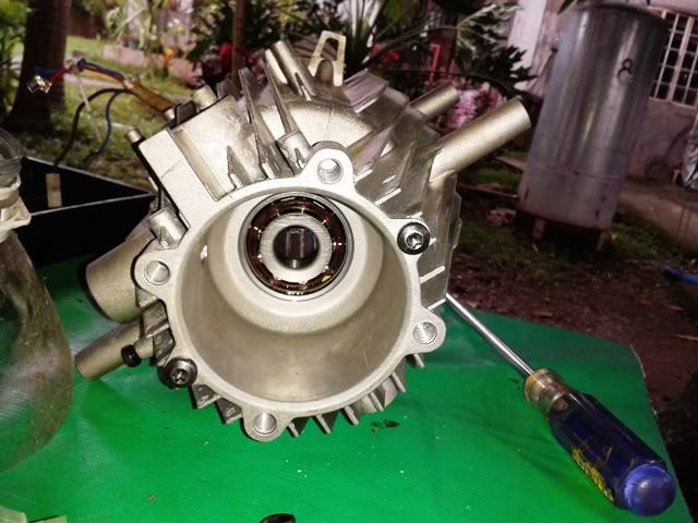
KarcherMotor.jpg


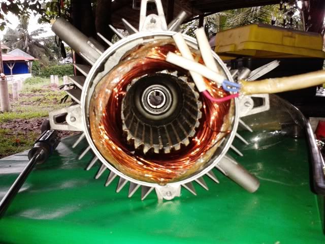
MotorStartingCoil.jpg

Starting Coil

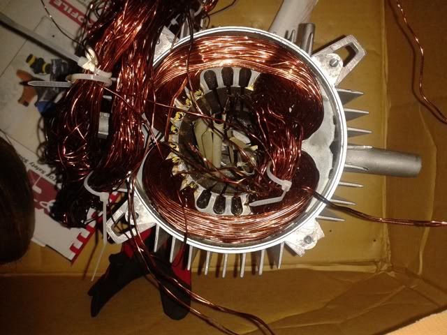
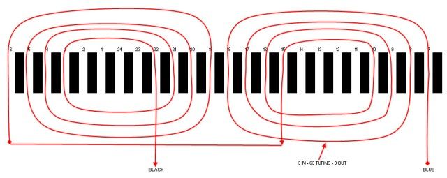
MotorRunningCoil.jpg

Running Coil
 
Replies continue below

Recommended for you

Rhatcher - if the pressure regulator is not enough to compensate the pressure that will be produce due to the 20% increase in rpm, I'm planning to increase the hole of the nozzle by 20%? thus to release or balance the produced pressure.
I’m not rhatcher, but I’ll give you my thoughts. Reducing the flow restriction is the right approach to reducing power consumption on a pd pump. And increasing hole size by 20% is what I would do as supported by simplistic calculations below:

For pd pump with 20% increased speed, your flow Q has gone up by 20%
Q2 = 1.2 * Q1

Let’s say the nozzle dominates the system pressure drop and nozzle DP is given by
DP~Q^2 / r^2 where Q is volume flow rate and r is radius of the hole

[we’ll focus on fluid power and neglect effects of efficiency which are harder to know]
Fluid power is given by
P = Q*DP = Q*Q^2 / r^2 = Q^3 / r^2

The change in power is estimated as
P2/P1 = (Q2/Q1)^3 / (r2/r1)^2
Using Q2/Q1 = 1.2 for pd pump at 20% higher speed:
P2/P1 = (1.2)^3 / r^2 = 1.73 / r^2

If you wanted P2/P1 = 1.2 (since you have uprated motor by approx 1.2), then
P2/P1 = 1.2 = 1.2^3 / r^2
1 =1.2^2 / r^2
r = 1.2
That tends to confirms your approach to increase hole size by 20%. If original motor was operating at appropriate margin to it’s rated power with original hole size, then rewound motor would be the same margin from it’s re-rated power with the new hole size.

We could also estimate the nozzle exit velocity using this hole size from V ~Q/r^2
V2/V1 = [Q2/Q1] / [r2/r1]^2 = 1.2 / 1.2^2 = 1/1.2 = 83%
(you will not have as strong a spray)

According to the thought process of zlatkodo, the original motor was already marginal and you may want to add back some margin rather than basing everything off the assumption that original conditions were properly designed. To add margin to magnetic saturation, make turns higher than 0.8 of original and motor not uprated so much, so P2/P1<1.2 you’d have to increase your hole size some more and get an even lower velocity than the 83% estimated above. Even if you kept turns at 0.8 but still wanted to add some more margin based on I^2^R heating you’d still increase hole size more and again end up lower velocity than estimated above. The calculations have simplifying assumptions and are not as useful as trying it out of course.

Pete - by the way the winding is lap and I will rewind it also with lap
ok, I guess you just drew it as concentric because it was easier to draw that way?


=====================================
(2B)+(2B)' ?
 
Wherever I said 0.8, should have said 0.83 i.e. 5/6.
Also I don't claim the calculation to be particularly accurate (I know there are more sophisticated models of orifices and nozzles available).

=====================================
(2B)+(2B)' ?
 
Pete - Thanks again, your point is well noted.

Trying to remove the old coils.....

motor3.jpg


motor1.jpg


2012-11-12200305.jpg
 
Richard888 and Pete,
My experience is with centrifugal pumps, not PD pumps. But, it is my understanding that a PD pump has a constant torque speed-torque curve. Thus, a 20% increase in speed only requires a 20% increase in power. If this is true, then the redesigned motor will provide the necessary power to drive the pump at the new speed without modifications. However, I am not certain of this so, maybe this is something that should be confirmed in the pump forum.

I understand zlatkodo's reasoning but I do not agree with it. First, it is based on the assumption that this motor's design is marginal. Without calculating the core flux densities, there is no way to know for certain if the flux densities are higher than normal. Next, and more importantly, if we are to assume that this manufacturer is squeezing every once of power out of the motor core that is possible, wouldn't it follow that all of this power is needed to operate the pump. Otherwise, why push the motor to the limit? Finally, this implies that if we reduce the motor power on the presumption that it will increase the motor life, then a modification to the pump would be required to reduce it's power consumption.

Reducing the pumps power requirement would reduce the pump's performance, perhaps to an unacceptable degree. For example, in this case we are looking at a pressure washer pump. The orifice may have a particular shape to achieve a desired spray pattern and it is certainly sized to produce a certain flow/pressure characterisic. If you change the orifice's characterisitics, the pressure washer's performance will be affected. Of course, I am not sure that changing the orifice size (or changing the pressure on the regulator) will reduce the PD pump power requirement. Perhaps this is another question that should be answered by the experts in the pump forum. In any case, reducing the motor performance and then reducing the pump performance to match is not something that I would endorse since I'm pretty sure that the outcome would be less than desirable.

On a subject that I am more experienced with, the winding diagram that is presented clearly shows a concentric winding. This is defined by the fact that the coils for each pole have different spans and are laid in with a common center. A lap winding will have all coils of the same span and the windings are said to be distributed because the coils for each pole do not have a common center. That being said, I'm not sure that I have ever seen a lap wound single phase winding.

Richard888's confusion may be because the original winding was installed as a lapped-concentric. For a lapped-concentric winding, the coils for both windings are laid in lap style at the same time, one coil side at a time, moving from left to right or right to left. When viewed from the end, it appears similar to a single layered lap winding instead of the two layers seen in a conventional concentric winding. But, the fact that the coils have different spans with a common center still defines a lapped-concentric as being a concentric winding.

Pete,
As I said above, I don't know if I've ever seen a lap wound single phase motor and I have never thought about redesigning a concentric single phase winding to a lap winding. My first thought is that I do not think that the lap winding redesign would be possible. My second thought is that it may be possible but it may also be more difficult than a sticking with the concentric winding. It is certain that you would still need a two layered winding, one start and one run.
 
I have confirmed that a PD (positive displacement) pump is a constant torque device. The constant torque motor redesign for 60hz will provide an increase in power equal to that required by increasing the pump speed. Modification of the pump will not be required.
 
I have confirmed that a PD (positive displacement) pump is a constant torque device. The constant torque motor redesign for 60hz will provide an increase in power equal to that required by increasing the pump speed. Modification of the pump will not be required.
Hi Ray. I will respectfully disagree on this point.

The volume FLOW rate Q increases according to speed (as I had stated). That much should be obvious thinking about the way a piston pump works.

The Fluid Horsepower or Brake Horsepower is given by
BHP = DP*Q
(That should not be a point for dispute. Electrical types may think of that as similar to P = I*E)

We cannot predict change in BHP with speed without knowing something about the system that the pump is attached to (as assumption about DP vs Q characteristics).

The only way to get BHP increasing by 20% when Q increases by 20% for a fixed system as you suggested would be if DP does not change with Q. I hope you'll agree that cannot be correct (would you expect resistor voltage to stay constant when we increase the current?).

You earlier made a statement that you expected P to go up by 1.2^3 for a fixed fluid system when you thought it was a centrifugal pump. To make such a statement requires an ASSUMPTION about the fluid system to which you connect the pump. The particular unstated assumption required is that the fluid system obey DP~Q^2. (Think about it, you cannot obey Q~N, DP~N^2 and P=DP*Q ~ N^3 without also satisfying DP~Q^2).

If we make the same ASSUMPTION for the pd pump, we would come up with the same conclusion. i.e. if we increase pd pump speed by 1.2 when connected to a fixed system which is ASSUMED to obey DP~Q^2, then the power must go up by
P~Q*DP
P~N*N^2
P~N^3
QED. All we needed to get there was to start with was Q~N which is true for PD pump and add an assumption about the system which we chose to be DP~Q^2.

The assumption DP~Q^2 system characteristic happens to be true for closed loop systems whose pressure drop is dominated by head loss from turbulent (vs laminar) flow. When you get into other flow regimes (laminar) it does not apply. When you have open loop system like pressure washer, with possible differences in elevation and velocity at entrance and exit, also does not strictly apply. With more info about orficie and entrance and exit conditions we could do better, but DP~Q^2 is a start and a traditional one at that.

Your reaction might be: "but wait Pete, those relationships P~Q, DP~N^2, P~N^3 are called "centrifugal pump laws" and so do not apply to PD pumps". It is true but in a different context. . When you ask a fluids guy what those relationships mean, he will tell you that they are NOT intended for predicting change of individual operating points with speed without knowledge of connected system (that would be folly.... operating point is intersection of pump curve and system curve and we CANNOT determine it without knowing or assuming something about the system curve). What those relationships are intended for is to map an entire pump curve from one speed to another. That particular mapping process applies to centrifugal pumps and not to pd pumps whose ideal curve is much simpler: a vertical line on DP vs flow graph.

In summary DP~Q^2 is an assumption. It is not perfect and could certainly be refined for orifices and entrance/exit conditions with more info. If we are going to predict change in BHP with change in speed for either type of pump (centrifugal or pd), we need info or assumption about the system. For both type pumps, we can predict BHP~N^3 if and only if we assume the pump is connected to a system which obeys DP~Q^2

=====================================
(2B)+(2B)' ?
 
Let's talk some more about pd as constant torque pump.
PD pump can be considered as a constant torque pump in some cases.
Which cases depend on the system that the pump is connected to.

As an example let's say I'm pumping between two large reservoirs at different elevations using a large diameter pipe.
The reservoirs are so large that their leve is considered constant.
The pipe is so large that the head loss is negligible.
The system pressures are set by elevation and unaffected by flow.
Then DP would be constant.
As we vary speed, BHP would change according to BHP~DP*Q
Since the problem assures DP is constant, and we already know Q~N, then we have
BHP~N
The constant proportionality constant is of course torque. i.e. constant torque in this particular application.
What made it work that way was constant DP as we changed flow. Reasonable for some systems, but probably not reasonable when forcing flow through a nozzle.


=====================================
(2B)+(2B)' ?
 
I was under the assumption that there was a pressure relief valve that may be used to limit the pressure rise and dump excess flow rather than forcing it through the nozzle. But I am not sure. Comment?

Bill
--------------------
"Why not the best?"
Jimmy Carter
 
Pete,
This pump has an internal pressure relief valve and an output pressure regulator, both located upstream of the discharge orifice. What would the system curve for this look like?
 
I left the PC on last night and did not refresh the screen before posting my comment. Now that I have posted, I see that Bill beat me to the punch with a similar comment. I guess we will both wait for a response.
 
IF it has a discharge pressure regulator which was limiting pressure at 50hz and continues to limit to the same pressure at 60hz, then it would be like the 2-reservoir pd pump example above: constant DP, constant torque, BHP increases by 120% when speed increases by 20% with no change in nozzle. Nozzle would perform identically as it did at 50hz, you would be just dumping more flow in the regulator and sucking more input power as a result.

=====================================
(2B)+(2B)' ?
 
Also a minor correction to my prior discussion, I should have used the term "Fluid Horsepower" rather than BHP throughout.
Pump efficiency changes are unknown in these scenarios, just focusing on fluid power.

=====================================
(2B)+(2B)' ?
 
I didn’t see that. It would probably either be a regulator adjustment (as discussed) or an adjustment to the pump swash plate angle (which could bring flow and pressure down and avoid wasting fluid power by dumping through a regulator).

=====================================
(2B)+(2B)' ?
 
ePete,

I am pretty sure it is just a crude regulator valve dumping back to the suction side. These little pumps don't have the sophistication found on a large industrial hydraulic pump. Maybe on the larger ones they do, but this one is either the top of the domestic range or bottom of the light commercial range where purchase cost get far more attention than operating cost.
 
Thanks Scotty, that makes sense. I have seen a lot of adjustable dump valves used for pressure control even in larger industrial systems. I only remember one that was controlled using adjustment of swash plate angle while running and it was for chemical feed pump. Thinking some more about that application, control of system volume flow rate (not pressure) was important for that application. That's not the case here.

=====================================
(2B)+(2B)' ?
 
Hi everyone.

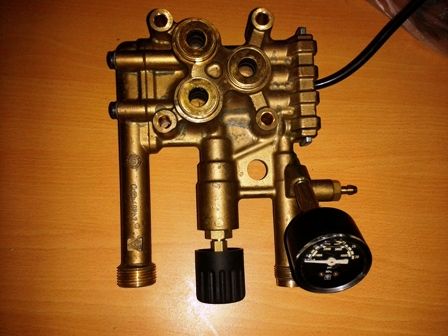
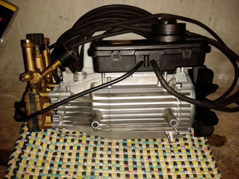
Here are some picture of the pump;

KarcherandSkil.jpg

New Skil (domestic series) as temporary replacement and Karcher (its a professional series

Reg1.jpg


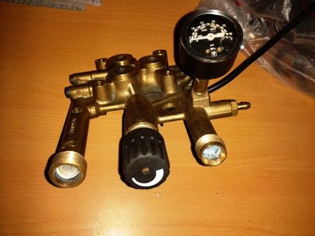
Pump.jpg

here is the pump showing the regulator knob

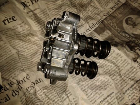
Piston.jpg

Pump piston

The user manual of the karcher states;

"Overflow valve with pressure switch - While reducing the water supply/quantity regulation at the pump head, the overflow valve opens and part of the water flows back to the pump suck side.

If the lever on the trigger gun is released the pressure switch turns off the pump, the high pressure jet stopped. If the lever is pulled the pump is turn on again."

My option to revise the orifice in the nozzle is not possible because the nozzle is different it has 3 orifices (with different profiles). Hope that the excess 20% rpm can be dissipated by the overflow valve. I really need to fast track this work so that we can see what will happen.

Thanks again.

 
The red unit looks like a toy - universal motor, plastic pump, short violent life followed by trip to landfill. The other looks like a light commercial unit, costs around £300 over here, say $400 maximum. Your labour time fixing it must be worth more than that, not to mention the downtime to the business where you and it aren't generating revenue. It's an interesting idea to rewind but perhaps not economically viable.

Have you checked ebay?


ScottyUK - That karcher was bought at USD1,500. We already bought a new Karcher for cleaning the A/C coils. I took the burnt one home for cleaning the cars but it seems that it will cost me much to rewind this so I bought a cheap USD100 washer. But still wanted to rewind this for curiosity (of converting it from 50Hz to 60Hz). It's my first time to open a electric motor and my first time to rewind it.
 
Status
Not open for further replies.

Part and Inventory Search

Sponsor