Eng-Tips is the largest engineering community on the Internet

Intelligent Work Forums for Engineering Professionals

RFI suppression in sensor wire 3

Status
Not open for further replies.

DDT12

Electrical
Apr 22, 2017
2
0
0
GB
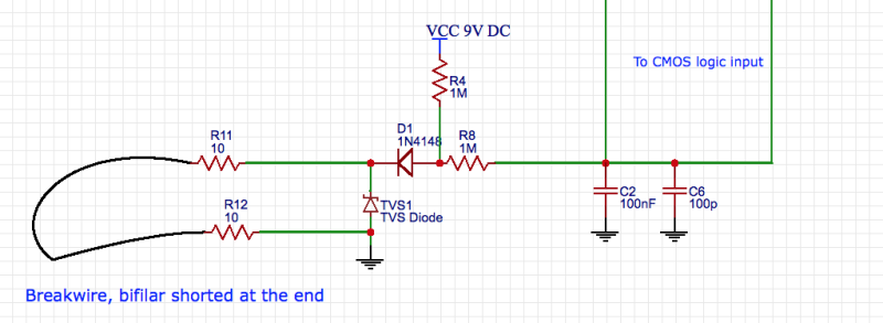
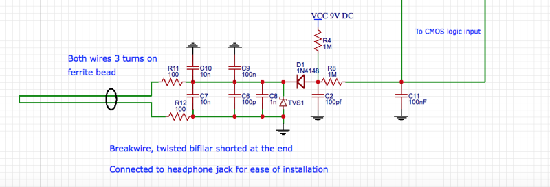
The following circuit is an input section of a break wire alarm. The sensor is a 20m long wire which activates the alarm when broken. The wire keeps the logic input low and when it's open the logic input goes high. The first priority in designing this circuit was robustness against false alarm due to RFI induced noise and low power consumption as it's powered by a 9V battery. Although the protection seems to be enough I'd like your input. Additionally, other suggestions regarding the design of PCB will be welcomed.

Sesnsor_input_pj84ul.png
 
Replies continue below

Recommended for you

You use of bi-fillar wire should give you a lot of RF rejection. For additional RF, a common-mode choke on the sensor wire will help with possible RF. This choke can be a single ferrite bead through which you pass both the R11 connection to D1 and the R12 connection to ground. For a little more rejection, use two or three turns, or buy one of the pre-wired small CM chokes. Maybe also move one capacitor to the junction of D1, R4, and R8

For cost, you could replace your TVS diode with another 1N4148, and maybe increase R11 and R12 to 100 Ohms.
 
Additionally...

You could add three bypass capacitors, across the wires plus two to ground, to the wire-side circuit before the diode D1, where any RF EMI would still be RF. After the (detector) diode D1, the RF EMI is effectively 'detected' to DC making rejection that much more difficult.

You could also add more capacitance at the gate input, to slow the response to the longest acceptable limit (perhaps 1 second?) to provide some rejection of short pulses such as neighbourhood lightning or human ESD.

All this depends on how critical is the application.

 
@VE1BLL and Comcokid, thanks for the inputs. Please check the updated circuit. Are the chosen cap values suitable? Since I am ordering the PCB do you think I should go with ceramic SMDs caps or regular leaded ceramic caps? I am asking because the rest of circuit is based on regular leaded components. The PCB is a regular two layer with copper plane assigned as ground.
Kindest regards
D

input4_duivtq.png
 
One step better would be to move your ferrite bead between C10/C7 and C9/C6. That way R11/R12 and C10/C7 filter first, and then the bead and C9/C6 filter again.

Z
 
The sensor input is really protected now.

In my opinion, capacitors of 1nF or less should be SMT with short trace runs, otherwise lead inductance largely negates the presence of the capacitor. Larger caps can be leaded since with their larger values they affect lower frequencies, and lead inductance is less an issue.
 
In some cases (not here), it's possible to use bypass capacitor lead length to your advantage; the inductance of the two leads being in a series resonance with the capacitor. Useful if you're notching out a certain frequency. I actually used this once, in a real application.


"Trip wire" circuits went out of use in war zones ans industrially 50 years ago.

Optical or other types of proximity detectors are far more reliable.
 
Status
Not open for further replies.
Back
Top