Continue to Site

Eng-Tips is the largest engineering community on the Internet

Intelligent Work Forums for Engineering Professionals

  • Congratulations SDETERS on being selected by the Eng-Tips community for having the most helpful posts in the forums last week. Way to Go!

RFS surface interpretation versus axis interpretation 1

Status
Not open for further replies.

gabimo

Mechanical
May 2, 2013
124
Is the surface interpretation taking precedence over the axis interpretation for features of size with no modifiers in the positional callout?

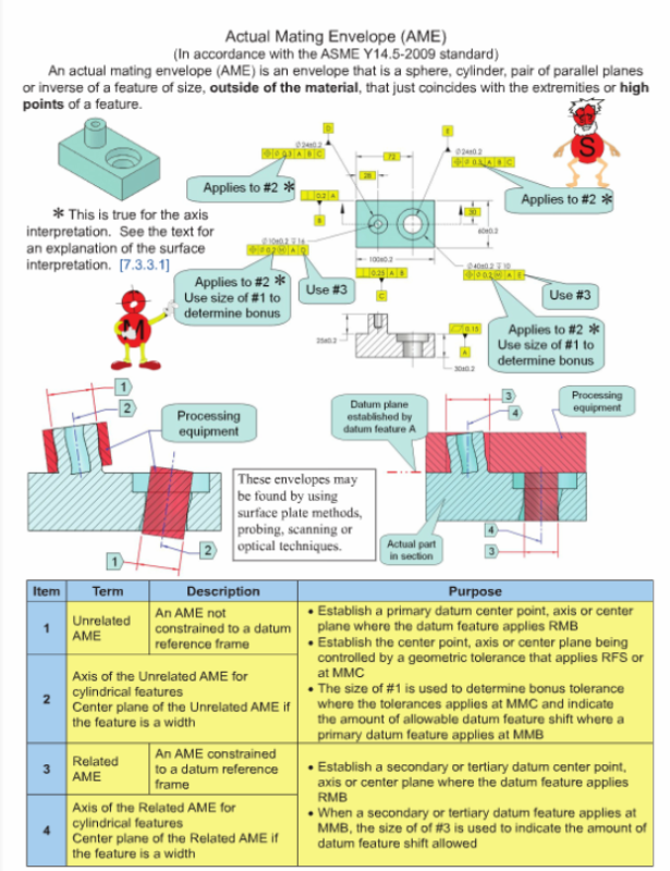
In other words, a hole positional callout RFS, does it have two interpretations, surface versus axis. So, if the actual surface of the hole does not violate the inner boundary (MMC minus geometric tolerance) the part is considered good even the axis of the unrelated actual mating envelope is outside the positional tolerance zone.

Am I correct?


Replies continue below

Recommended for you

As far as I can find ASME Y14.5-2009 only speaks about surface vs axis interpretation in section 7.3.3.1, which explains positional tolerance at MMC. The standard states that surface interpretation takes precedence over axis interpretation when holes are positioned employing the MMC modifier.

I do not see why this would not hold true for holes specified at RFS. The inner boundary is not constant, though, due to the RFS tolerance and depends upon the size of the hole in question. Therefore, the gage would have to be adjustable. Here you would need to determine the UAME (size) of the hole first, in order to know the correct gage pin size to represent this hole's inner boundary (UAME of hole - position tolerance = inner boundary).

I could be wrong...
 
I have an impression that boundary is only defined in connection with virtual/resultant condition, so, no boundary at RFS. Could be wrong as well... :)

"For every expert there is an equal and opposite expert"
Arthur C. Clarke Profiles of the future

 
Attached is the first page of Appendix C of Y14.43 (gaging standard). The highlighted blue reads to me that you cannot gage to RFS ("...the actual axis of a part datum feature shall be used for inspection..."). The highlighted yellow reads to me that you can gage to RFS, it is just impractical.

Here is a thought experiment. I have a plate with a hole in it. The process used to make the hole makes a perfectly consistent size, as in zero tolerance. However, this process cannot hold the location of the hole perfect. We only need to verify the position of the hole during inspection. Can you gage this part? I would say yes. The size of the pin on this gage would be determined by subtracting the position geometric tolerance from the size of the hole. So if the hole was specified as ø.250 +/- .000, position of Ø.010 A,B,C the gage pin would be size Ø.240 and we use surface interpretation to inspect the hole. Is this any different than gaging a hole at RFS? We simply need many different gages/or gage pins and select the appropriate pin based upon the hole size.
 
 http://files.engineering.com/getfile.aspx?folder=02b561be-38df-4c07-9afd-e07050eb48a1&file=appendix_C_y14.43.pdf
2.8 APPLICABILITY OF MODIFIERS ON GEOMETRIC
TOLERANCE VALUES AND DATUM FEATURE REFERENCES
RFS, MMC, and LMC may be applied to geometric tolerance
values on features of size. See Figs. 7-34 and 8-24.

RMB, MMB, and LMB may be applied to datum feature
references. Rule #2 RFS applies, with respect to the individual
tolerance, and RMB applies, with respect to the
individual datum feature reference, where no modifying
symbol is specified. MMC, LMC, MMB, or LMB shall be
specified on the drawing where it is required.
NOTES:
(1) The following paragraphs describe the principles based on an
axis interpretation for RFS, MMC, and LMC. In certain cases of
surface deviation of the feature, the tolerance in terms of the
feature axis or feature center plane may not be exactly equivalent
to the tolerance in terms of the surface limited by a boundary.
In such cases, the surface interpretation shall take precedence.
See para. 7.3.3.1(a) and Fig. 7-6.
 
From 2009:

7.2 POSITIONAL TOLERANCING
Position is the location of one or more features of size
relative to one another or to one or more datums. A positional
tolerance defines either of the following:
(a) a zone within which the center, axis, or center
plane of a feature of size is permitted to vary from a true
(theoretically exact) position
(b) (where specified on an MMC or LMC basis) a
boundary, defined as the virtual condition, located at the
true (theoretically exact) position, that may not be violated
by the surface or surfaces of the considered feature
of size.
 
So, do we have a conflict within the standard?

"The following paragraphs describe the principles based on an
axis interpretation for RFS, MMC, and LMC. In certain cases of
surface deviation of the feature, the tolerance in terms of the
feature axis or feature center plane may not be exactly equivalent
to the tolerance in terms of the surface limited by a boundary.
In such cases, the surface interpretation shall take precedence"

VERSUS

" (b) (where specified on an MMC or LMC basis) a
boundary, defined as the virtual condition, located at the
true (theoretically exact) position, that may not be violated
by the surface or surfaces of the considered feature
of size."

 
In another thread, one of the best GD&T gentlemen --pmarc---wrote:

"- ASME - when applied at RFS position tolerance is interpreted in terms of axis of the feature. When applied at MMC and LMC it can be interpreted in terms of axis or in terms of surface (the draft of the future version of Y14.5 standard puts much more emphasis on surface interpretation being the "better" one for position at MMC and LMC)."

Now, my follow-up question is: does that mean that postion RFS CANNOT be interpreted in terms of the surface of the feature (surface interpretation)?

pmarc,
Could you help, PLEASE?

HAPPY EASTER!!!! Have a good egg hunting!


I know this was discussed in the link that Nescius provided but I still don't see why surface interpretation could not be used for RFS as long as the UAME of the feature in question is known.

I have attached a page from the Meadows text. In this example he shows a technique for calculating the position used by a hole feature and then comparing it to the allowed position error to determine if the hole feature is to print or not. Why could not this technique (slightly modified) be used for surface interpretation of a hole at RFS?

1) Determine the UAME of the hole.
2) Determine the inner boundary that cannot be violated by the surface of this hole (UAME - Position RFS value = inner boundary)
3) Put a gage pin of inner boundary size (calculated in step 2) at true position.
4) If the hole fits over this gage pin then this hole has used less than the allowed position error and is therefore good.

Sorry if I'm beating a dead horse...
 
 http://files.engineering.com/getfile.aspx?folder=08f0ac8e-b687-4f81-b5ce-93aff2365caf&file=inpsection_of_part.pdf
Capture_UAME_asrsmk.png

Picture from Tec-Ease website


pmarc,
"Applies to #2*" note is shown on both callouts: position RFS and also on position at MMC
What do you think?
 
greenimi,
No, that does not mean position at RFS can't be interpreted in terms of surface of feature. As mentioned by AndrewTT and in the other thread, there are ways to verify this type of callout without taking the axis of the feature into account.

My statement from the thread where some of the differences between ISO and ASME systems were discussed was of a general nature. I think we will agree that the Y14.5 standard, as is now, strongly implies (for example through the wording of paras. 7.3.2 vs. 7.3.3.1) that the only way to interpret position tolerance at RFS is to use axis interpretation.
 
pmarc, do you think that the ASME standard uses language that strongly recommends/prescribes the use of axis interpretation for RFS because they are concerned that people would use surface interpretation incorrectly with RFS (due to the lack of a constant boundary)?
 
AndrewTT,
Unfortunately, I don't know what they are concerned about. Maybe the lack of constant boundary is indeed the reason.

The fact is that in the draft of the new version of the standard there is clear statement in para. 5.8.2:
"The surface method shall take precedence where the tolerances are applied at MMC or LMC. [...] The surface method is not applicable where tolerances are applied RFS."

So looks like in a near future we will not be having this type of conversation (whether it is allowed to interpret position at RFS in terms of surface or not) at all.
 
pmarc said:
"The surface method shall take precedence where the tolerances are applied at MMC or LMC. [...] The surface method is not applicable where tolerances are applied RFS."

So looks like in a near future we will not be having this type of conversation (whether it is allowed to interpret position at RFS in terms of surface or not) at all.

So the fun (ambiguity) will be gone! Harder and harder to have fun these days!
 
I forgot to say Thank you pmarc.
Better late than never.
 
AndrewTT said:
1) Determine the UAME of the hole.
2) Determine the inner boundary that cannot be violated by the surface of this hole (UAME - Position RFS value = inner boundary)
3) Put a gage pin of inner boundary size (calculated in step 2) at true position.
4) If the hole fits over this gage pin then this hole has used less than the allowed position error and is therefore good.

ASME Y14.5.1M-1994 provides basically the same definition as you describe for the surface interpretation of RFS position tolerances applied to holes. Additionally, it states that the surface interpretation shall take precedence over the resolved geometry (axis, in this case) interpretation if the results differ.

I find this rather odd because both ASME Y14.5M-1994 and ASME Y14.5-2009 seem to require the axis interpretation, and in fact don't even mention a surface interpretation, for RFS position tolerances.

I believe it is possible for the results of the two interpretations to differ by up to two times the size tolerance, so I am glad the Y14.5 draft clearly states that there is only a single interpretation for RFS. I wish they would go a step further and eliminate all mention of an axis interpretation for MMC and LMC, but I'm not holding my breath.


As a side note, I believe it's possible to simulate the axis interpretation for RFS position tolerances using hard gaging as follows:
[ol 1]
[li]Get a bushing that has length equal to that of the hole, has a known fixed inside diameter, and has a variable outside diameter that expands to match the UAME of the hole.[/li]
[li]Install and expand the bushing in the hole.[/li]
[li]Get a pin that has outside diameter equal to the bushing inside diameter minus the RFS position tolerance value.[/li]
[li]Attempt to place the pin through the hole in the bushing at true position.[/li]
[li]The tolerance is met if and only if the pin fits.[/li]
[/ol]

pylfrm
 
I think the surface interpretation for RFS is not usable. To determine where the surface is allowed to be means knowing what the size is, but the modifier indicates to ignore the size.

The axis interpretation is good for when the location tolerance is greater than the feature size. Say a dia 0.250 hole with a position tolerance of dia 0.500 MMC. It's hard to functionally gage that, so one has to resort to looking for the axis. Typical use would add a perpendicularity tolerance or, if it's a pattern, a positional refinement, but the initial evaluation can't use a hard gage as would work for a dia 0.010 tolerance.
 
So I have been telling people at my work that you can gage to RFS (hard gage with variable components) but it will be more expensive and have more potential for operator error than gaging to MMC (hard gage with fixed components). Based upon this discussion and what is written in Y14.5-2009 I am thinking I should correct that message to say that you cannot gage to RFS. Or, I suppose I could just amend the message to say that any "gage" made to check features at RFS would need the ability to have variables data measurements taken. So it would be more of a measurement fixture than a gage. Bottom line, use axis/center plane interpretation (resolved geometry) for RFS features.

Does anyone know what the ISO standard(s) says concerning this topic?
 
AndrewTT said:
Does anyone know what the ISO standard(s) says concerning this topic?

I don't know that, but I know who knows:) [bigsmile]

pmarc,
Could you help us again, please?
 
Status
Not open for further replies.

Part and Inventory Search

Sponsor