Eng-Tips is the largest engineering community on the Internet

Intelligent Work Forums for Engineering Professionals

Rigid bus simplified short-circuit calculation 1

Status
Not open for further replies.

b_gibb

Electrical
Apr 13, 2023
14
0
0
CA
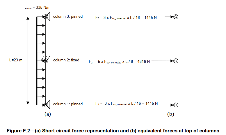
I'm trying to follow the IEEE 605 example for calculating the cantilever force on a rigid bus insulator due to short-circuit. I understand the example with the exception of how they determined the equivalent forces (F1, F2, F3 in Figure F.2) from the Fsc.

Example:
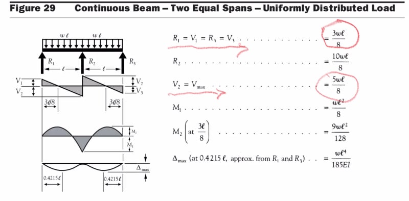
F3 = 3 x Fsc_corrected * L / 16. Where did the constant 3 and 16 come from? Same for F2 (where did constants 5 and 8 come from?). See pictures.

2023-09-18_13_19_48-IEEE_605-2008_Bus_Design.pdf___-_Foxit_PDF_Editor_hrfoex.png

2023-09-18_13_14_30-IEEE_605-2008_Bus_Design.pdf___-_Foxit_PDF_Editor_cjzkj8.png
2023-09-18_13_15_52-IEEE_605-2008_Bus_Design.pdf___-_Foxit_PDF_Editor_sovcjk.png


ben
bengibb.ca
powerdesignerpro.com
 
Replies continue below

Recommended for you

The table 18 is to determine the maximum span length between insulator supports.
The reactions on the bus supports insulator are determine by other structural calculations based on a uniform beam load with selected support (boundary) conditions P, F, C.
The 3/16 and 5/8 come from structural calc and loading diagrams similar to the one shown below.

IMG_1162_m3fwlt.jpg
 
Although the calculation -in IEEE 605-e is done for the cantilever
the explanation for the beam supported at two ends can be considered. Thank you, cuky.
 
Status
Not open for further replies.
Back
Top