Eng-Tips is the largest engineering community on the Internet

Intelligent Work Forums for Engineering Professionals

  • Congratulations waross on being selected by the Tek-Tips community for having the most helpful posts in the forums last week. Way to Go!

Rigid Connection without Steel Column

Status
Not open for further replies.

GaryHStr

Structural
Jul 12, 2022
8
0
0
GB
Hi guys,

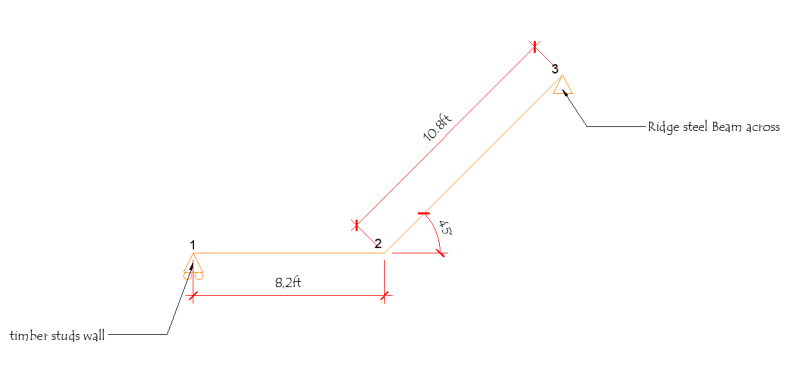
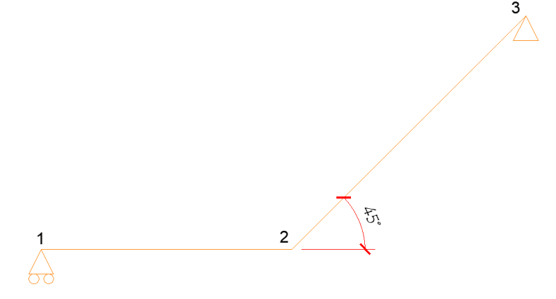
I'm currently working on a project where the client has requested the removal of a steel column, and I am tasked with designing a rigid connection to replace it. The project involves connecting two steel beams at point 2, with a span of 8.2 feet from point 1 to point 2 and a sloped section of 10.8 feet from point 2 to point 3.

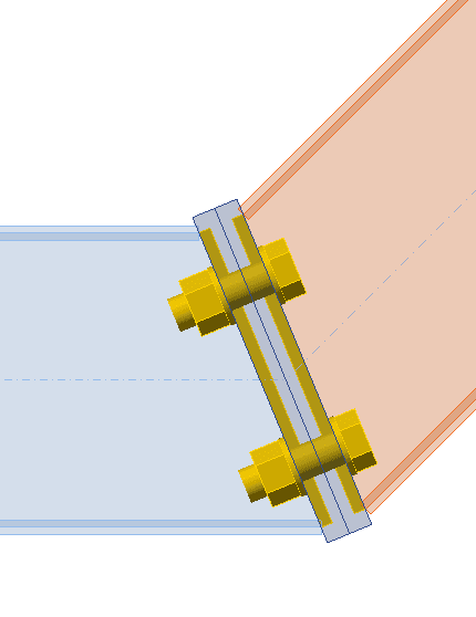
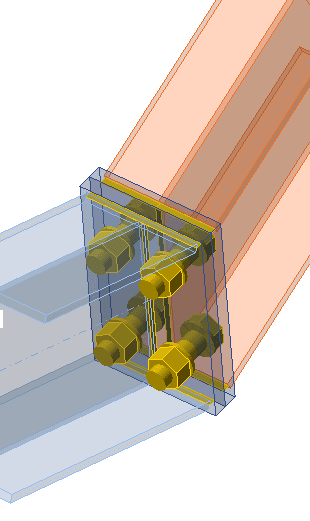
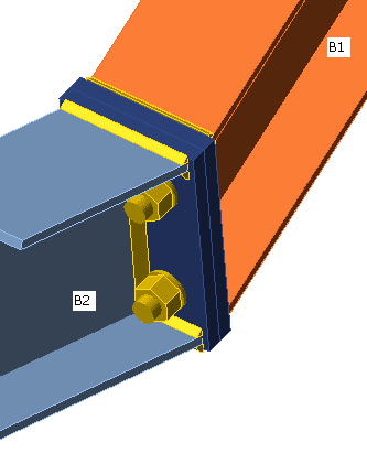
I have designed the steel beams as continuous beams with satisfactory sizing. At the connection point 2, I have utilized two plates bolted together with four bolts and welded to the beams, which also appears to be satisfactory. However, I would greatly appreciate your input to ensure that I am not overlooking any critical factors in the design.

Thank you for your assistance.

Sketch_sigvvo.png
 
Replies continue below

Recommended for you

Can you show a dimensioned sketch of the actual designed connection?
The bolts are not going to pick up any load until the welds fail.
Presumably your sketch is a side view, correct?
Is there a deflection limit criteria?
 
The end connection at either 1 or 3 needs to have some kind of rotational restraint or else the beam will be unstable in torsion. Though, it would help to see the actual support / beams and how you propose to connect them.
 
Thank you for your prompt response and valuable feedback. I appreciate your insights. Please accept my apologies for not mentioning this initially. I have attached an image showing the connection details for your reference.

In the image, you will see a side view of the proposed connection. Additionally, the beam at point 1 is supported on a timber stud wall, and the beam at point 3 is intended to be supported on the ridge beam across.

I would also like to inform you that the design includes a maximum allowable deflection limit of 10mm.

Please review the attached sketch, and I look forward to your feedback.

Thank you again for your valuable contributions and prompt response.

Sketch2_xbmykd.png


Connection_gnukwa.png
Connection_2_ejmolt.png
Connection_3_qxuuba.png
 
Are you going to weld the two angled end plates together? or just bolt them?
Using bolts in tension is not ideal; bolts should be used in shear.
If you need a bolted connection for assembly reason, suggest some sort of welded up connection fitting between the two beams with fasteners in shear thru the webs and flanges.
You will have compression on one side of the I beams; need to check for crippling.
 

Still trying to visualize the sketch...My question, is ; Are the beams B1 and B2 coplanar? ( at horizontal plan)?

If so, torsion will develop at the beams and the set up will not be stable ..

If the beams are not co-planar, substantial moment would develop at pt.2 and the connection shall be moment resisting conn. Literally , the bolt set up at the end plate will not be satisfactory to resist moment.


I cannot give you the formula for success, but I can give you the formula for failure..It is: Try to please everybody.

 
With torsion, pinned connections at 1 and 3 may be a problem.

-----*****-----
So strange to see the singularity approaching while the entire planet is rapidly turning into a hellscape. -John Coates

-Dik
 
Its an end plate moment splice similar to Chapter 3 of AISC Design Guide 16. These can be designed as fully rigid and bolts in tension is not a problem we do it all the time. Depending on your plate thickness you may or may not need to consider prying action. Maybe some extra considerations to make due to the inclined beam on one side of the connection but looks pretty straightforward to me.

You can improve the strength by using an extended plate, adding stiffeners to the plate, and having bigger bolts.
 
They are not ideal for cases like this where there could be significant prying on the attachment with a small number of fasteners. Can lead to two part fractures of the connection as opposed to fastener hole bearing yielding in a shear joint which won’t result in separation.

Obviously there are many cases where tension loaded bolts work well. This case does not look like a good one for this type of connection. Unless the plates and fasteners are well oversized and fasteners torqued to a high level this joint is not likely to be rigid.

 
XR250 said:
Did not know that? Can you explain further? Billions of working designs would tend to disagree.
Agreed.

SWComposites said:
They are not ideal for cases like this where there could be significant prying on the attachment with a small number of fasteners.
Sure you should consider prying, that is normal.

SWComposites said:
Can lead to two part fractures of the connection as opposed to fastener hole bearing yielding in a shear joint which won’t result in separation.
I'm not what the point here is. Fastener hole yielding is normal but if you exceed the bolt strength in a shear connection you will still have failure.

SWComposites said:
Unless the plates and fasteners are well oversized and fasteners torqued to a high level this joint is not likely to be rigid.
If your definition of 'rigid' is to achieve full stiffness of both members being joined then I agree with you. The ASI design guides don't recognise this connection as a suitable moment connection for this reason, whereas I believe AISC and British standards find this connection acceptable.

If however you are happy with a connection that is mostly rigid, but doesn't achieve the full rigidity of the connecting components then this connection works perfectly fine.
 
I'd move the splice away from the corner and have it fully welded.

Best will in the world, there's every chance it won't sit flush and the bolts will be pulling the end plates together. At least with an orthogonal end plate splice this effect is reduced.
 
GaryHStr,

I see from the screenshots you posted that you're using IdeaStatica. Using the software you can investigate the moment rotation of the joint to see whether it classifies as fully rigid or as semi-rigid. If it's partially rigid, then there is guidance provided in Eurocode 3 on what to modify your analysis to account for the flexibility of this connection, but this isn't really recommended.

I would look to SCI P398 guide for the proper design of moment resisting connections and stay within those parameters.
 
GaryHStr:
Some of us might call that a ‘cranked beam.’ With the dimensions of 8' horiz., by 10.67' at 45̊ on the slope, that rafter or beam would be about 4' wide on a shipping trailer, eminently shipable. I would shop weld that joint and be done with it. Design it as a cranked beam of course. In describing an engineering problem, dimensions matter, so do general loadings and their magnitudes, they give an experienced engineer some idea of the actual problem. You know, 100lbs. is a lot different than 100tons from the design standpoint and gives some idea of magnitude of the problem and the detailing involved. Then, you deleted the picture which actually showed what you were trying to design. Describe your problem (a word picture) so I can draw that picture, and only that picture, not 10 others also, to fit that description. For example, I have a roof beam which runs right, 8' horiz. from an ext. wood stud wall, on the left; then it slopes up a different roof plane at 45̊ and 10'-8" (sloped length) to a perpendicular steel ridge beam on the right. The ridge beam connection is assumed pinned and the stud wall support is assumed to slide or move perpendicular to the wall, etc.
 
Status
Not open for further replies.
Back
Top