Eng-Tips is the largest engineering community on the Internet

Intelligent Work Forums for Engineering Professionals

Rigid Frame Bridges 3

Status
Not open for further replies.

tmalik3156

Structural
Jun 21, 2021
92
0
6
CA
Hello
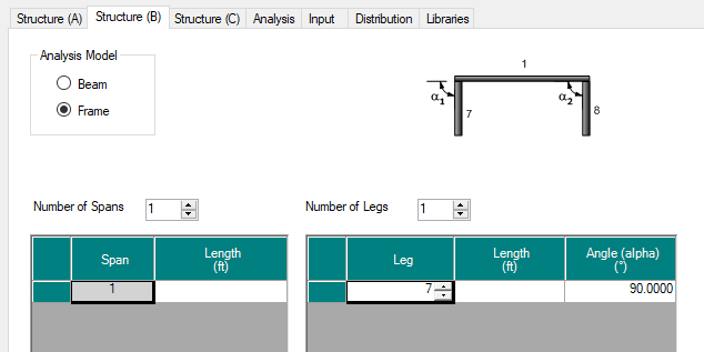
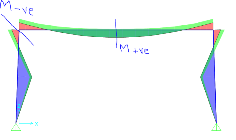
I am looking for guidelines/example calculations of Rigid Frame Bridges. So far I have found only two ancient books (Hayden, PCA). If anyone can name textbooks, or provide links to online resources, I will highly appreciate it.
 
Replies continue below

Recommended for you

You might try looking for "integral abutments", "full retaining abutments" or "integral leg superstructures". "Rigid frame" is not a term typically used for bridges, because they are rarely, if ever, designed that way.

Rod Smith, P.E., The artist formerly known as HotRod10
 
Thank you very much for the suggestion.
By Rigid frame bridge, I mean to describe a slab bridge (typically having a parabolic soffit) constructed monolithically to high walls.
An example is in this photo:
On the contrary, if I search for Integral Abutments, I get information for girder bridges that are integrally connected to short abutments resting on flexible piles. This is not what I am looking for.
 
Ah, what you you describe is what's generally referred to as a 3-sided box culvert or a bottomless box culvert. They're not generally used for spans over 20'; there's probably a reason for that.

Rod Smith, P.E., The artist formerly known as HotRod10
 
Well, they can have a much longer span.
This one in Canada is 108 feet.

They are not culverts but real, full-scale bridges of single or multiple span. Unlike culverts overs water, they are mostly found at grade separation of intersecting roadways.

This one for example is two-span (each span 69 feet)

Anyway, I am surprised that there isn't any significant resources to be found regarding design of these bridge. I am interested if books or design examples are available anywhere.
 
Long span integral full retaining abutment bridges never were very common, and are even more rare now. The closest we've come to something like that is a long span concrete arch (commonly referred to as a Bebo arch structure). I would guess that finding a design example is going to be difficult. A basic moment frame analysis would suffice for the preliminary design, but a more efficient final design would probably require an FEA. I like a good challenge, but I'm not sure I'd want to tackle one of those.

Rod Smith, P.E., The artist formerly known as HotRod10
 
That style of bridge was common in this area, I know exactly where the first one linked is. Up until recently, practically every bridge over a motorway with 6 lanes or less in Ontario was that style. Lately, with widening of main highways, the only thing they have been doing with those is ripping them out. I doubt if many bridges of that style have been built since the 1970s. Historical records?
 
There are 100's of rigid frames in the NYC area but they've lost popularity because of cost and difficulty in building one over an existing roadway. I haven't seen any books on rigid frames other than Hayden or the PCA manual, which is still valid.

 
They never caught on out in the western US, so I guess I didn't realize there were so many back east. Anyway, if you have design guides from when they were popular to build, that may be all the help you get. If you're designing a new one, it'll probably be cost-effective to create a detailed FEM for it. You'll probably need to consider how to mitigate the temperature differential associated with "mass concrete" placement.

Rod Smith, P.E., The artist formerly known as HotRod10
 
BrianPetersen,
Interestingly, the opposite is also true - Ontario is replacing girder bridges with precast rigid-frame bridges!
bridgebuster,
Found PCA manual online. Will look into it, thanks.
BridgeSmith,
I am evaluating an existing one, not designing any new one. But I thought to understand this type of bridge better, design examples would help. In particular, the earth pressure and temperature effects are certainly different from girder bridges sitting on bearings on top of abutments.
 
In particular, the earth pressure and temperature effects are certainly different...

For sure. For most bridges, we can ignore the effects of earth pressure, and only consider the effects of temperature in evaluation of the bearings and expansion joints. For a rigid frame, it might take some thought to figure out where those effects should be considered and at what level, if they reduce the stresses in some areas.

Rod Smith, P.E., The artist formerly known as HotRod10
 
I have load rated a few older ones (all conventionally reinforced slabs) but never designed what the OP showed in the video. Are these being PT'd in Canada? There are a few older ones around our city but not a lot. Essentially you have a pinned base and moment continuity at the top between the superstructure and walls. Like BridgeSmith said, a 3 sided culvert but longer span. A skewed condition certainly will complicate things.

Rod, interestingly enough, BRASS-GIRDER does accomodate these. It's under the Control Option for Structure (B).

Untitled3_lyufat.png
 
Yes, STrctPono BRASS-Girder will do the analysis of the frame, and it's fairly straightforward. The more difficult aspect of the design is in applying the loads and resistances of the soil. The conservative approach would be to apply no passive resistance to counteract the loads on the span, but then apply full soil pressure with the minimum dead load on the span. How conservative that approach is, is difficult to say.

Rod Smith, P.E., The artist formerly known as HotRod10
 
Working in Washington DC, they have a lot of longer span older rigid frame structures that I have load rated. Easy to analyze but there isn't any software that can perform a load rating so it's all done with spreadsheets to calc out the capacity of the variable depth span.


there isn't any software that can perform a load rating...


If you properly account for the soil loading/resistance, or ignore it, BRASS-Girder will provide load ratings.

Rod Smith, P.E., The artist formerly known as HotRod10
 
tiny_nzztod.png
MIKE 311 said:
it's all done with spreadsheets to calc out the capacity of the variable depth span
Do you only check capacity of the deck ? or the vertical wall too ?
I have a situation where the mid-span capacity exceeds positive moment demand (that's good)
End-span capacity exceeds the negative moment demand (that's good)
But the negative moment demand on top of vertical wall exceeds its capacity there. What do we do in this case ? Any suggestion ?
 
tmalik3156 said:
Do you only check capacity of the deck ? or the vertical wall too ?

You are supposed to check the walls also.

A few thoughts....

1. How are you calculating your effective section strip width? This is one category where I have implemented different strategies that I feel are reasonable and do not blindly follow the provisions of AASHTO for slab bridges.
2. What kind of boundary conditions or earth pressures are you applying in the model that you have shown above?
3. Are you utilizing the effects of the axial force on the walls? This will actually provide you a small additional amount of capacity. Think of the interaction diagram for a column with bending and a small amount of axial load.
4. I'm all for trying to tweak the model and play with the numbers to try and get a load rating to come out (within reason) but how old is this structure? Sometimes a load rating factor less than 1.0 can be warranted. However, if the structure is in great shape and is showing no signs of distress then I would be suspect about giving it a deficient rating. The fee on the job is also going to heavily influence how much tweaking I would be willing to do.
 
STrctPono

1. I am taking 1 m width in analysis. So my Finite Element (SAP2000) frame model is 1 m wide perpendicular to the page.
2. Triangular earth pressure with Ko = 0.5 (coefficient of earth pressure at rest)
3. I did not check P-M interaction.
4. The rural bridge (over 60 years old) was inspected, and no significant sign of distress on the wall was found.
 
@tmalik3156 - I have a load rating calculation for a 54' concrete rigid frame bridge - was done in the 90's using AASHTO Standard Specs - that I could post if you think it would be of use.
 
Status
Not open for further replies.
Back
Top