Eng-Tips is the largest engineering community on the Internet

Intelligent Work Forums for Engineering Professionals

Rigid Square Section Supported by C-Channel

Status
Not open for further replies.

tKc74

Mechanical
Jan 31, 2021
20
0
0
AU
Hello, a problem I'll try to conceptualize best I can:

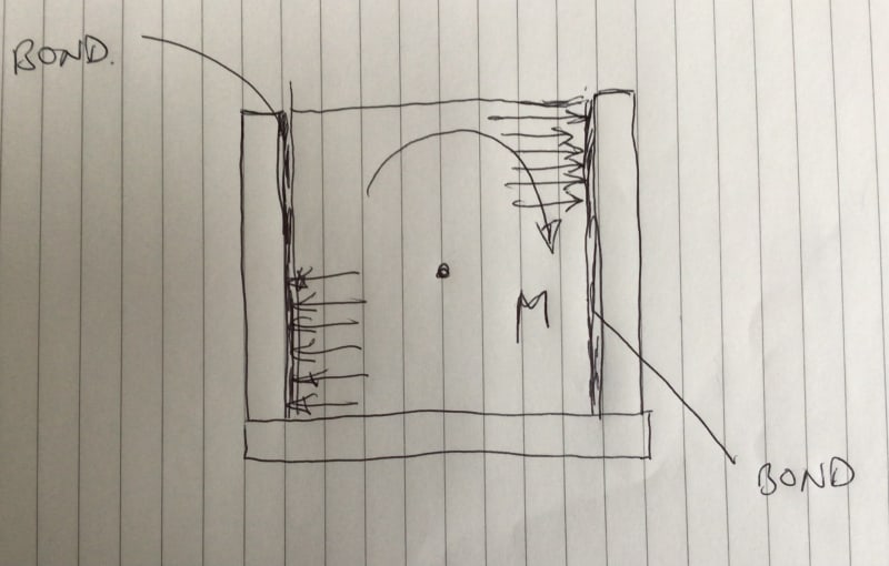
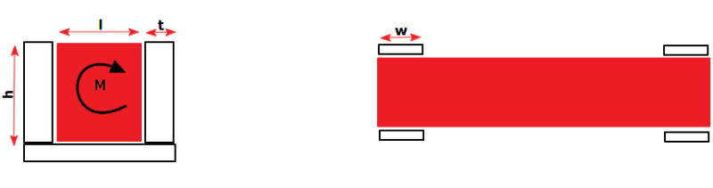
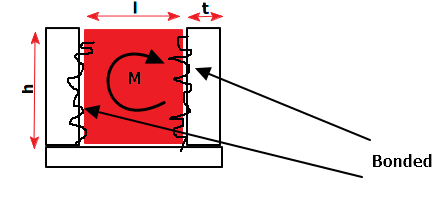
Let's say I have a rigid solid square section that is bonded on both sides of the flanges at both ends by a c-channel of length width W, flange thickness t, gap (and square dim) l and flange height h (see below illustration).

A moment M is applied to the square tube and equal stress is developed in both c-channel flanges. What is the proper way to evaluate the stress in these flanges.

Pic1_y3gqpl.png

[ol 1]
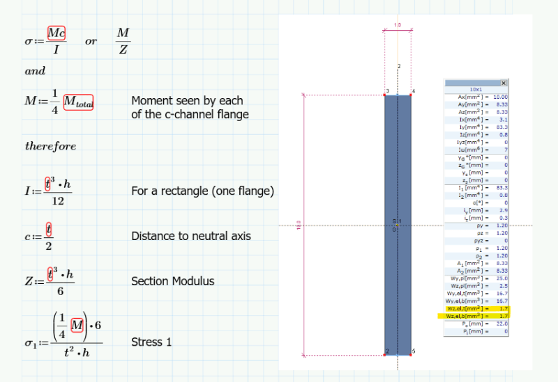
[li]Evaluate each flange separately (4 total) and assume only 1/4M goes thru each c-channel flange, however the section modulus is based on the individual flange (poor).[/li]
Pic2_v8runc.png


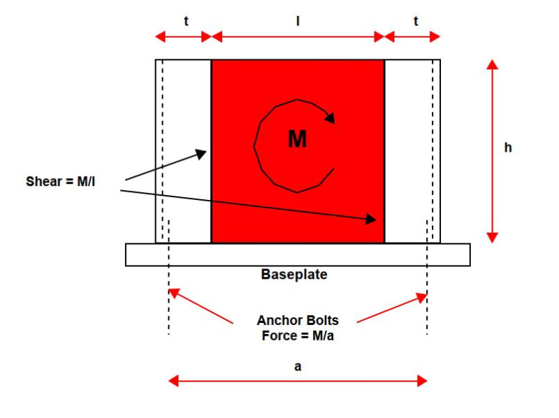
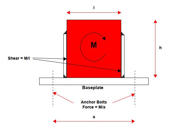
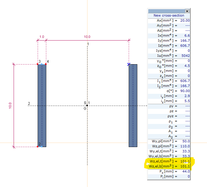
[li]Evaluate each c-channel as a whole. Assuming just the flanges take the load and not the base (conservative) the moment will be 1/2M for each, however the section modulus will be much higher. This will obvs depend on the separating distance l (example below uses 10), if evaluating it this way the 2x moment will be dwarfed by the additional area being further away from the centroid fairly quickly.[/li]
[/ol]
Pic3_bwbb38.png


What's the correct way to evaluate the bending stress in the c-channels, or have I totally missed the mark?

“If the women don't find you handsome, they should at least find you handy.” - Red Green
 
Replies continue below

Recommended for you

The rigid square section is bonded to the inside face of the flanges (as mentioned in OP). Illustration below to make that clearer.

Pic4_pu7k8z.png


“If the women don't find you handsome, they should at least find you handy.” - Red Green
 
Hi tKc74

The weakest part will be the bonding between the channel and the square, so I would look at the shear strength of the bond between the square and the channel.

Just out of interest what happened to the other problem you had with the large fabrication where you were considering welding and fasteners, what did you do in the end?

“Do not worry about your problems with mathematics, I assure you mine are far greater.” Albert Einstein
 
Hiya,

Yeah, I will look at the bonding separately (different issue :p), trying to localize and focus on the flange(s) of the c-channel currently and how to show the stress in these, I'm thinking it’s either scenario 1 or 2 as I mentioned in the OP, just need some convincing.

Yeah, the large fabrication went well, did its service with no problems (no cracks in the welds or sheared fasteners), had to do some last-minute changes as per the structural engineers request to increase some of the custom cut I-Beam's sectional modulus, particularly where the pickup points were low, but in the end, it was successful, thanks!


“If the women don't find you handsome, they should at least find you handy.” - Red Green
 
Hi

Thanks for the update, well the way I see it is if the bonding fails then the square section will twist and contact the channel flanges however they will have different moments on the flanges because as the square twists assume clockwise, then the square will hit toward the top of the flange on the channel at the right hand side and the bottom side of the left hand flange, so moment on each side if you treat the flanges like a cantilever will have loads at different points.


“Do not worry about your problems with mathematics, I assure you mine are far greater.” Albert Einstein
 
Assuming the bonding doesn't fail (not trying to focus on the bonding, assume square section is one with the channels), the square section will try to bend both the flanges, do you evaluate those flanges separately or combined as per items #1 and #2 in OP? Or by some other method

“If the women don't find you handsome, they should at least find you handy.” - Red Green
 
Hi tKc74

Are the flanges of the channel welded or is the channel a drawn section.
Either way the flanges on each side will be loaded at different points see sketch, I guess if the channel is a drawn section you would analyse it as one s but in my opinion I would check the shear strength of the bond. If the bond fails is the result considered a failure of the component?
38C7E007-180F-440A-A613-C63B0E94B3C2_bssemk.jpg


“Do not worry about your problems with mathematics, I assure you mine are far greater.” Albert Einstein
 
The simplest would be to simply add a baseplate under each end of the square section, but if the square section is an HSS, it has rounded corners, which require special welding treatment.

Using channels, I suggest using the sketch below. That way you can develop the full section of the channel, rather than relying on the flanges alone.

Capture_ie8nzr.jpg


BA
 
rather_be_riding said:
How are the C-channels constrained in turn? At the base or at the cross-sectional end? I'm guessing the base but you know what they say about assumptions....

Both the base and the cross section. Could use a vertical plate in lieu of each channel.

A simpler detail is illustrated below. Each plate carries a tension or compression of M/l:

Capture_mygucs.jpg


BA
 
@BAretired - I was asking the OP rather than you, sorry. Could have been clearer. How the OP has the end arrangement constrained in turn has some bearing on the stress experienced within it.

I think the stress in the plate is a tad more complex than evenly distributed across the length and/or width - I'd probably guess the same for the bond for that matter. I'd expect the edge closer to the centre of span to be more highly stressed than the opposite end depending on the various stiffness of the components and the bond etc. I'm also assuming this is 'bonded' not welded as @BA has shown.
 
Status
Not open for further replies.
Back
Top