Continue to Site

Eng-Tips is the largest engineering community on the Internet

Intelligent Work Forums for Engineering Professionals

  • Congratulations KootK on being selected by the Eng-Tips community for having the most helpful posts in the forums last week. Way to Go!

Rim Joist - Shear Transfer

Status
Not open for further replies.

Ambemily

Structural
Jul 2, 2018
20
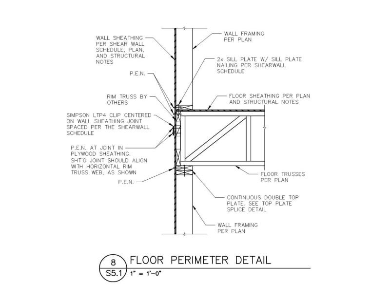
I have a question for you all about rim joists and shear transfer. Typically, I design the wall sheathing to break at the top of the top plates and then attach LTP4 clips at the joint to transfer the load through the joint. My client, however, wants to place the joint mid-height of the rim joist. I've said this was okay and have detailed it as a continuous solid LVL rim joist. They have now started using rim joists as trusses, instead of the LVL. The rim joists have a horizontal web, as shown in the attached image, which is where the sheathing breaks. The truss engineer is wanting to know if the truss needs to be designed for the shear load or not, as if it does need to, it fails. My client is freaking out over this so i'm trying to dig deeper into this. The shear load only goes through that horizontal blocking, and then back out of it, less than 1/2" away, so the entire truss wouldn't feel the shear transfer, is that correct?

I'd love to hear input on whether or not the rim truss needs to be designed for the full shear load here.

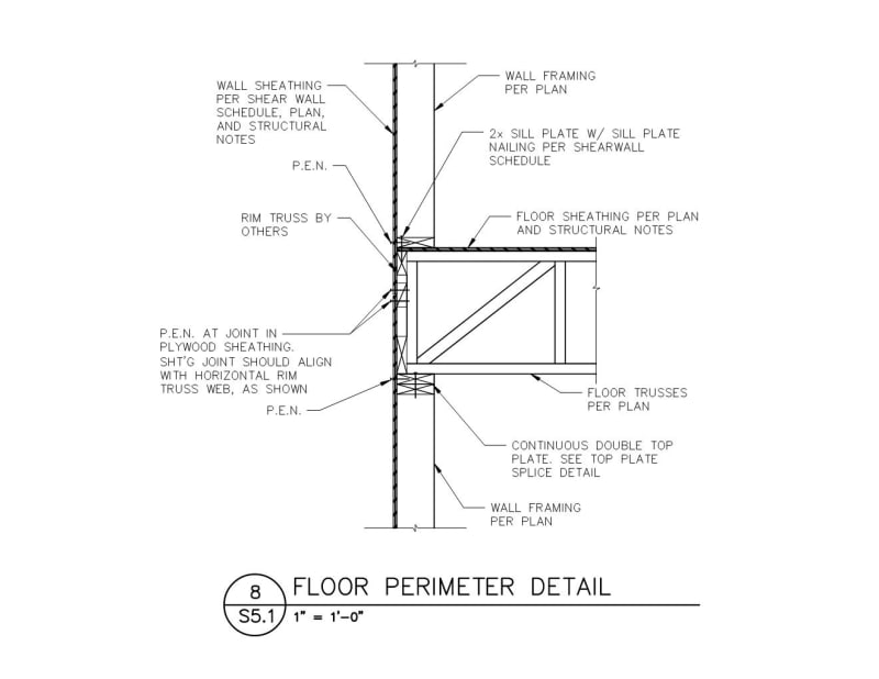
rim_joist_elevation_z5oidf.jpg
Rim_Joist_ss3tda.jpg
 
Replies continue below

Recommended for you

If there isn't a direct connection between the sheathing panels across the joint, then the shear would go through the web of the truss.

If you have a longitudinal 2x that the upper and lower sheathing panels are attached to, then the shear transfers through the connections of the sheathing to the 2x and the 2x itself. As long as the cross section of the 2x and the sheathing-to-2x connections are adequate, that takes the truss web out of the load path.

Ok, sorry. Taking a closer look at the details, it appears the rim truss is right behind the sheathing. That makes it more difficult to get shear transfer across the joint. However the shear on the truss still flow through the truss only the distance between the screws at the edges of the sheathing panels. It doesn't seem like it would be too much for the truss members. Generally the limit on the shear force that can be transferred across a joint like that, is the capacity of the screws, not the capacity of the lumber.

Rod Smith, P.E., The artist formerly known as HotRod10
 
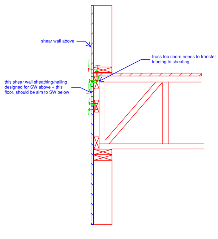
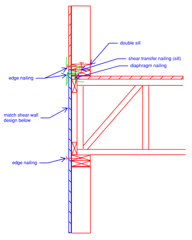
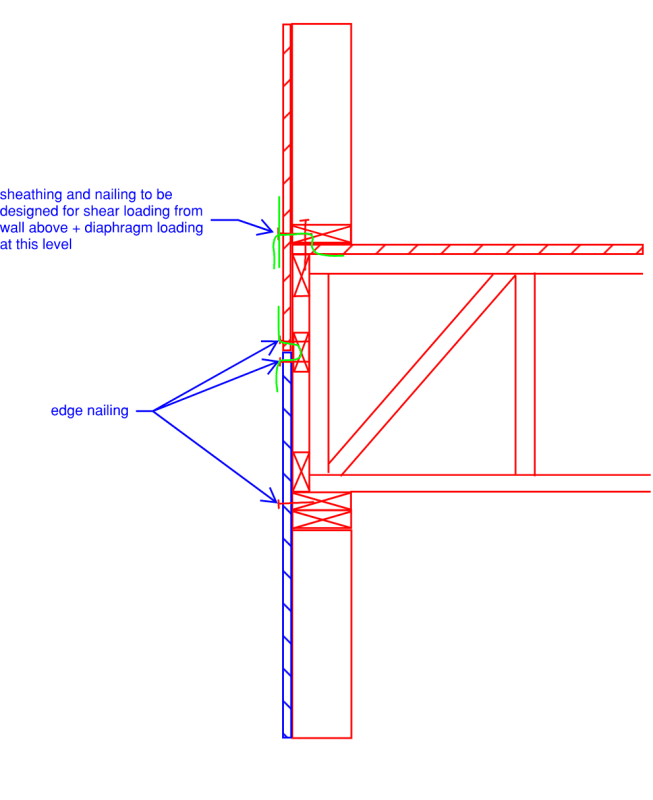
You could design to avoid the truss, however as shown it does not appear to be detailed as such. How does the shear loading at the floor diaphragm get to the wall below? I have included a few sketches of ways I see that this could work.

How are you dealing with vertical loading, are the truss web members aligned to studs (doubt they will be when installed in the field), does the truss top chord need to be designed for bending, are there column loads? Shear is only a part of the issue, vertical load carrying capacity is another.

Are there any fire wall assembly issues with this? Is there a specific UL? Is fire retardant lumber required, can they FRT the trusses? Just another consideration.

Light green below indicates load path.
Img_3_-_Copy_jizfox.png

Img_1_-_Copy_cfrgej.png

Img_2_-_Copy_gjmbt5.png
 
Another note, technically the truss acts as a shear wall (vertical studs), so the lumber needs to match what you designed the shear walls with, in my area trusses are almost never the same species as what the EOR designs the building for - this can cause issues with clips and other connections as well. Also note that their may be some limiting factors with the wood being "flat", so you may not get proper nail penetrations into the verticals and therefore the shear wall capacity may not be correct, something to check.

Overall it is my opinion that this is a bad idea and you should consider maybe shear panels instead of rim joists if they are against rim joists.
 
Aesur,
On your 3rd sketch, since the shear goes through the web of the truss, would that truss need to be designed as a drag truss? Alternatively, what if the truss designer did not put a web here and instead I had them install 2x blocking. Then, the truss would not need to be a drag truss as the load goes through the 2x blocking instead, correct?
 
I should have drawn that with that piece in the middle as blocking with a single / instead of the X; lack of sleep from our newborn is catching up to me. I would think that piece is just blocking as you said and doesn't indicate that the truss itself is a drag, the top and bottom chords of the shear walls would be the sill, blocking and top plates.
 
If I were to add LTP4 clips, as shown, at the sheathing joint, do you believe that the shear path would now be through the LTP4 clip and not through the rim truss and the rim would not need to be designed for the full shear force?
Rim_Joist_2_w1vtdd.jpg
 
The LTP4 helps, but only handles tension, not compression, I assume you would technically have some compression to consider there?
 
Neglecting gravity....

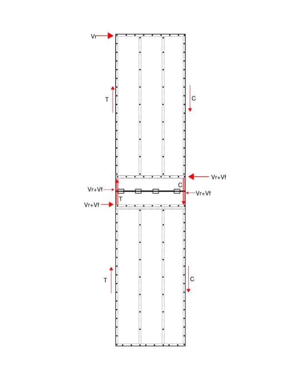
I guess I can try to break this down in the image below. Shear forces on upper level are tension and compression at ends and shear at top and bottom. Same for the lower level.
The shear at the rim will be the shear at the bottom plate (assuming floor and roof loads all go through the plate) and then an equal and opposite shear at the bottom of the sheathing joint. That shear would transfer through the LPT4 clips to the lower plywood panel joint and into the lower wall through a shear load at the top plates. There will be tension and compression forces at the ends of the rim only, which I could resolve by a strap and some vertical blocking at the end.

Thoughts? Am I missing anything? I guess with this breakdown I'm neglecting any actual rim and just transferring the loads through the sheathing. Any problems with this?

wall_layout_dxssx6.jpg
 
I agree with most of your sketch, however, what you show essentially has a plywood shear panel as a "cantilever" without an edge chord in the rim space. You would need the blocking and vertical studs (truss web members) to match the shearwall stud spacing (16" typically) for the plywood to achieve published values and achieve proper nail penetration to supporting members; unless you know of some kind of testing that says you can stich splice plywood panels in a blocked shear wall together with clips only. Additionally if you look at local shear forces in the sheathing, you will find both tension and compression at that connection.
 
Status
Not open for further replies.

Part and Inventory Search

Sponsor