Eng-Tips is the largest engineering community on the Internet

Intelligent Work Forums for Engineering Professionals

RISA HELP-BEGINNER 3

Status
Not open for further replies.

Vish S

Mechanical
Mar 21, 2024
12
0
0
US
RISA1_egfnn4.jpg
ACAD_sag3cq.jpg
RISA-BLC1_brru7f.jpg
RISA-BLC2_aownlh.jpg
RISA-SLV_ucdooc.jpg
RISA-RESULTS_mhi9zf.jpg


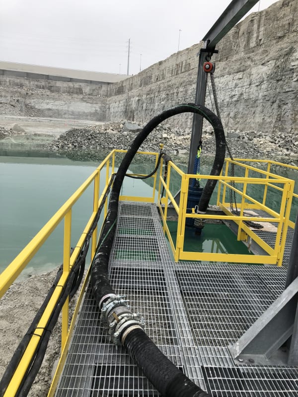
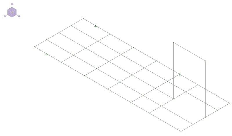
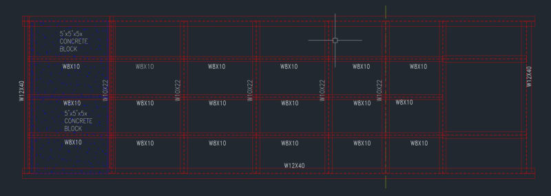
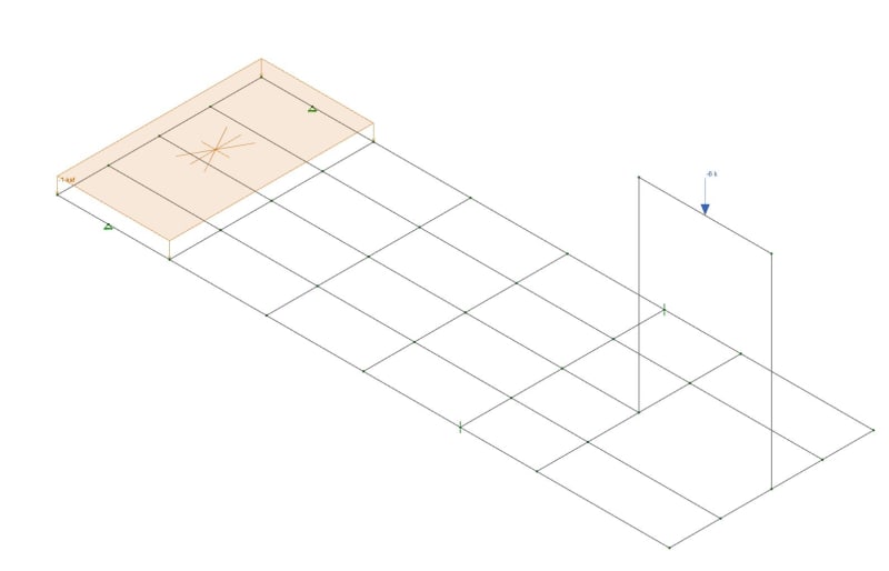
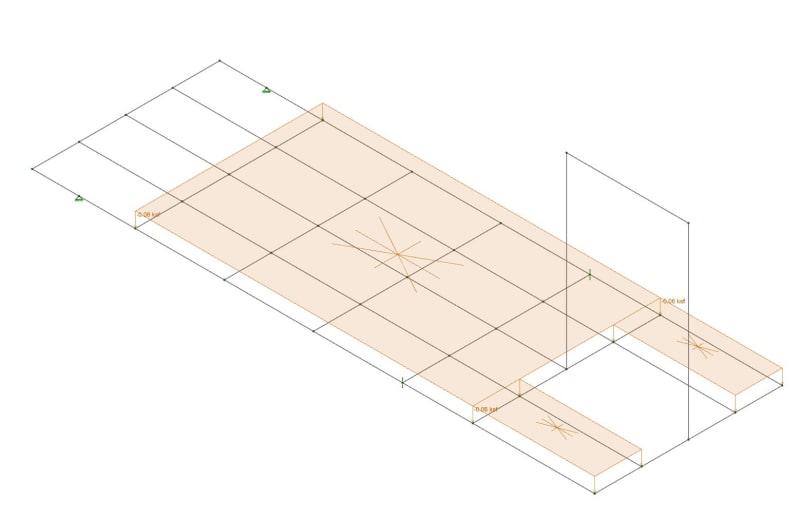
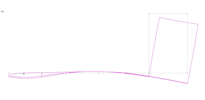
I am new to RISA and taking over a project from a guy who left the company. This project has a platform with grating all around except at one end (See image2). Currently, in the opening on right side of ACAD image, there's a crane suspended pump and to counter it on left side there's 2 5 ton blocks. Now, the pump is being replaced by vertical turbine pump which approx. weighs 2500lbs more than previous one. So I am trying to figure out how much more counter weight I am supposed to put so that the platform isn't tipped over. If you look in image2, the platform is on ground till the yellow phantom line and is suspended in air yellow phantom line onwards. The RISA file the previous guy built I am not sure is quite right or what more modifications are required to make the project feasible. I ran the model with existing conditions. I have the attached them as well. I have below questions:

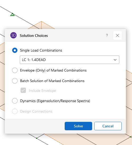
1) What option should I use when I solve the model?
2) Practically, when the pump is installed the platform should be straight, in RISA when we have the results should show minimal or no deflection on the side with pump right?
3) I ran the models by increasing the counter weights on the left but the result is same so need some more modifications but not sure what am I supposed to do.

Any help on this appreciated, any more information needed do let me know.

- Vishwa
 
Replies continue below

Recommended for you

Just some quick Q's:

- Looking at your model, why a concrete block if you have a support underneath it already? Can the support under the concrete block not resist the uplift? I believe the presence of the supports underneath the load for your concrete block is why your results don't change when upping that weight.

- Looking at your handle -> (Mechanical) <-, why have you been tasked with trying to do this in RISA? I think you'd do better if you started out by drawing a free body diagram, to determine your overturning situation.

Please note that is a "v" (as in Violin) not a "y".
 
WinelandV is correct. You have supports which take the load, so the counterweights are not truly balancing the pump load.

Go to View Results and turn on your Y reactions. You will see vertical reactions at the four supports. Determine if these make sense based on what the framework is connected to.

DaveAtkins
 
Regardless of whether you have a support underneath of the concrete blocks aside, the deflection of the frame past the other column that supports the pump will deflect essentially the same. The counterweight will only prevent uplift at the backside, it will not prevent beam deflection at the pump.

In fact, adding the additional concrete load only increases the actual load on all 4 columns. If the rear two supports under the concrete weight can take some uplift, is the additional concrete even necessary?
 
WinelandV, DaveAtkins & jayrod12
There's no supports underneath the platform. The left side of the platform beyond the yellow centerline in image2 is on the ground and the right side is suspended in air. The 2 pins shown in RISA model I have no clue why they were put in by the previous person who built the model. If I get rid of them and try to solve I get an error. One thing I am going to try is DaveAtkins' suggestion of taking the Y reactions. I will also try to put fix reactions on the nodes as majority of the platform is on ground.

WinelandV : This new job is majority structural and I will be using RISA a lot but I am from Mechanical background so I put Mechanical in my handle. I should change it to Structural if it allows me.

Below is a picture of it currently is. The chain hoists and support structure will be removed also and the new pump will be installed by crane.

2018-12-20_10.29.08_p2dn4t.jpg
 
Like I said a ton of unknowns here for any of us to truly be helpful.

Is this dunnage just resting on the ground adjacent to the body of water?

The RISA model is completely inaccurate.

“ If I get rid of them and try to solve I get an error.” yes because the model is unstable without supports, boundary conditions are essential to a structure model.

For a grillage on earth you’d need to look into continuous spring supports and probably significantly reduce the stiffness of the springs for several feet adjacent to the body of water accounting for the saturated soil being “mushy”
 
Vish,

I still recommend a hand sketch, draw in the different load locations, and figure out how much concrete weight you need based on OT at the yellow line.

As for the Q of "can the members take the additional load", that's more complicated. RISA is a powerful program, and it's actually quite easy to make it give you the answers that you want, but not necessarily the right answer.

Now the background question: Do you have training/education in structural engineering, or was all of your education in mechanical? If it's the latter, there's so much to learn, that you will need a mentor for (and that's before getting into "what are the in-and-outs of using RISA"). If your education was in structural engineering, then you should probably start by reading through the entirety of RISA's help file.

Please note that is a "v" (as in Violin) not a "y".
 
WinelandV,

In this situation, according to you what kind of boundary conditions would be there?

My background has been entirely mechanical engineering and 10-4 on the mentor part. Next week I have scheduled something with someone who uses RISA on day-to-day basis. I did go through some basic RISA training but this is much more advanced than what I went through.
 
If you have to utilize the RISA model, I'd go with Celt83's springs, set them to be compressive only, and put one about every foot along the W12x40's. But that leads into the question of "how stiff should the springs be?"

What exactly are you trying to determine? If it's the new weight of concrete to hold the frame down, determine the overturning about the yellow line from the pump. Multiply that by 1.5 to get the required OT resistance. Figure out where you want your concrete centroid, and determine the volume required to hit that weight (concrete in this instance is probably only 145 pcf, unless you're going to put more r/f in there than I would anticipate).

If you're using the model to try and estimate deflections, we're back at the spring modeling Q of "how stiff". If you're trying to use RISA to check the member capacities, then that's a trip down steel design lane (I recommend the Salmon & Johnson steel design text book, but I'm probably biased b/c they're from UW-Madison), before getting into "how do I adjust the member parameters in RISA".


Please note that is a "v" (as in Violin) not a "y".
 
" determine the overturning about the yellow line from the pump"

disagree with this approach, the yellow line is the water edge and should absolutely not be used as the pivot point. For a quick hand check IF this thing is completely ground supported I'd assume a pivot point about 1/3 the distance away from the counter balance centerline towards the yellow line.
 
To me it looks like this model is using a simplified approach where the vertical support is the pivot point and the upwards vertical reaction at the pinned "support" would be equivalent to the required counterweight. Couldn't really confirm that without more info though.
 
VishS said:
I did, but all I got was that they don't do individual projects like this.

Wow, that sucks. Back when I was there, we would help new users a lot. Just to get them comfortable with the program. Help them along. We wouldn't give them step by step instructions. But, we'd listen to them. Figure out what they were trying to do and point them in the right direction.

Then again, that's one of the reasons why there current management wasn't happy with me. I was focused more on pleasing the customer than on maximizing profits.

My personal opinion is that WinelandV's advice about adding in compression only springs is probably good. You might add in a more flexible "tension only" spring or two at a couple of places as well.... Just to keep the program from reporting an instability. But, make it 1/10 or 1/20th the stiffness of your compression springs.

Caveat: I was the former VP of Tech support / Engineering for RISA. I was there for almost 16 years before I left in late 2017... When the original owner sold the company to a cold / heartless (IMO) foreign conglomerate. The entire culture of the company changed in the final months that I was there. It was very sad for me. I should point out that my opinions on the company (and their management) are my own. Based on my positive and negative experiences there. I've been threatened with lawsuits (indirectly), so I have to point out that I have very little 1st hand knowledge of what goes on their day to day anymore. Very few of the employees I worked with are still there. Though I do hear from some RISA users who contact me privately about their experiences with the new iteration of the company.

I also now work for one of their competitors (Computers and Structures Inc). So, that's another reason why I can be considered biased on the subject.
 
Also, DaveAtkin's advice of visually reviewing your reactions is always good advice. If you can makes sense of statics of the applied load vs reactions, then you should have a good feel for how your model is behaving.
 
I don't think springs are necessarily useful here. These support conditions are very conservative for the members, but unless they're failing and need to be modeled less conservatively, I'd think adding lines of springs will mostly just make it more annoying to determine the required counterweight.

Vish S, is the concrete the counterweight? Or is there just a concrete deck that the counterweights are placed on?
 
Here is a purely fictitious 2D model to illustrate some points:
Top model - Compression only supports, first support some distance away from the water. First support acts as the pivot counter weight highly effective

Middle model - linear compression only springs with a "soft" spring region adjacent to the water. Dunnage beam is moderately flexible. The apparent pivot point moves much close to counter weight reducing it's effectiveness

Bottom model - same as middle but the beam is now very rigid. Model moves closer to rigid body motion the pivot point moves closer to the body of water but still considerably further back than the top model.

Screenshot_2024-03-22_141817_o01phz.png
 
If it were me, I would determine the required counterweight using a pivot point at about the middle of the dunnage span away from the start of the cantilever over the water.

If this is at the bottom of a quarry and sitting on a solid rock base then I'd run with the compression only support model with one node defined as horizontal restraint which will come from friction of the dunnage against the ground. I would load this model with the counterweight determined from the step above and the design the system with and without the crane at the free end loaded. I'd probably place the first compression only support 5-6 feet away from the water as a gut feel move.
 
Status
Not open for further replies.
Back
Top