Continue to Site

Eng-Tips is the largest engineering community on the Internet

Intelligent Work Forums for Engineering Professionals

  • Congratulations KootK on being selected by the Eng-Tips community for having the most helpful posts in the forums last week. Way to Go!

RISA Industrial Platform Design

Status
Not open for further replies.

StrucPEng

Structural
Apr 23, 2018
95
I am using RISA for the first time to design an small industrial platform that will be used for man access to mechanical equipment (Note mechanical equipment is independent of the platform and does not impart a load on the platform). The reason I am doing this in RISA this time is the platform beams are not nice and concentric with the columns of end and intermediate frames. I also do not have much opportunity with the equipment below to add any braces in one of the directions.

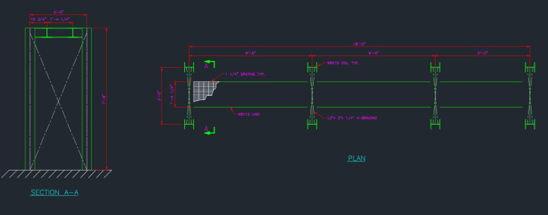
The platform dimensions are noted in the attached sketch along with RISA results (3 ft wide, 18 ft long, 7.5 ft high platform). I am not seeing very large loads or deflections in any of the members or joints which I find promising but I am cautious that I might be missing something. The design constraints and assumptions are as follows and my questions are below.

Constraints:
- Platform width is driven by access between piping so no opportunity to make it wider.
- End and Intermediate frames have less restrictions space wise and are wider.
- I only have the ability to add bracing in one direction as shown.

Assumptions:
- 100 PSF LL
- 10 PSF (Bar Grating) + Self Weight & Handrail DL
- Lateral Loads of ~2% of factored vertical loads at each node in both X & Z direction. (This is based on ASCE 7 1.4.3, I believe it is fairly conservative given ASCE calls for 1% of Dead Load)

Questions:
- With the relatively small loads and deflections is it reasonable to have bracing in only one direction and utilize the stiffness of the columns and base plate connection to develop the loads in the X direction? (I am hesitant to assume the base plate connection is in reality "fully fixed")
- Is there anything that sticks out in the model view that doesn't look right?
- Any general tips using RISA for design.

I appreciate all the help and input!
Thanks
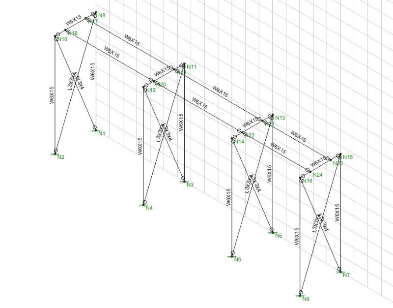
Model_View_ukzpd7.jpg

PLAN_AND_ELEVATION_ji04rf.jpg


Replies continue below

Recommended for you

I've done many small industrial platforms like this. I'm not surprised you're down to minimum sizes; that is typical as you'll often be controlled by simply what's readily available, easy to weld up, and gives you enough dimensions between flanges to work with.

Your model appears setup correctly; however I'd change your lateral, notional load. At 2% of 7.8 kips total vertical force you're only applying 156 lb. Someone resting a bunch of plywood against the platform can generate more load than that.

I'd design the platform laterally around what I've seen all the time; someone attaching something to the columns that wasn't intended. Most platforms such as these have way more steel than required and the mill-wrongs know this. They'll attach pipes, monorails, chainfalls, safety tie offs, you name it to the columns.

Put a large lateral load onto a single post; something like 2,000 lb. This should take care of someone bumping it with a forklift or resting a section of fabricated pipe on the platform or whatnot. Make sure your anchor bolts can take this moment at the base of the columns.

I might delete the angles and fixed bases and just let them weld everything into moment connections. Your loads are likely small enough that the platform doesn't need anything fancy to transfer moment across those joints and unless your region is one of the ones that wants to bolt everything they'll happily just weld everything anyway.

If you're new to RISA, make sure you're using the proper steel code. RISA can't tell if you're using ASD or LRFD for steel unless you select it.

Ian Riley, PE, SE
Professional Engineer (ME, NH, VT, CT, MA, FL) Structural Engineer (IL)
American Concrete Industries
 
To answer your questions:

1) I don't see an issue with a moment connection about the X-axis as long as you design your baseplate for the moments and whatever is acting as your foundation can handle the forces.

2) If you notice in your reactions you have moment about the X-axis, this is because you have the columns fixed at the bottom and a fixed boundary boundary condition. I am assuming you don't want any moment about the X-axis, since you already have X-bracing. I would change the boundary conditions to free about the X-axis. As for anything else, it is difficult to know without seeing the model.

3) As for tips for using RISA, I recommend watching the videos online that RISA has created. They were very helpful to me when I was first learning RISA. They show a bunch of things I don't think I would ever of figured out on my own.
 
Agree with TME on the welded option - but I would keep the angle braces. If the site conditions permit, I would shop assemble each frame and install in one piece. The W6x15 beams that run the length of the platform, in your CAD screen shot you show them at the same level as the transverse W6x15 beams - can you run those over top of the frames and use (1) W6x15 at 18'-0" long? The continuity of that beam will give you a bit more lateral stiffness and reduce the demand on your moment connections at the base. You'll end up with a bit of torsion in your beam to column connection, but for the size/loads given (and if you can shop weld the frames) that shouldn't be an issue.
 
I will offer the same tips I say to anyone in our office who comes to me with a model question.
1. Do your node reactions looks correct, do you have reactions where expect?
2. What do the shear diagrams look like, are they as you expect? can see real quick were you have a translational release as shear will be zero.
3. What do the moment diagrams look like, are they as you expect? can see real quick were you defined fixity or missed hinges as moment will not be zero.
4. What does the deflected shape look like, and again is it as you expect? The nice thing is almost all of the software packages now can animate the deflected shape so you can see oddities develop.
5. If a lateral resisting element what does the axial diagram look like, ie do your braces have axial only, axial at all?

rinse repeat 1 thru 5

RISA has some great tutorial videos.

Open Source Structural Applications:
 
Why are intermediate frames needed?
Eighteen feet is not a long span for a platform, especially since it is less than 18" wide. Too long for longitudinal W6s, but light W12s or maybe even W10s would have plenty of strength (section modulus) and rigidity (moment of inertia).

Revisit the 1 1/4" grating. The image shows bearing bars parallel to the longitudinal beams. Either intermediate grating supports will be needed to limit span of the bearing bars (even if the four frames shown are used) or turn the grating 90 degrees so that bearing bars are supported by the longitudinal beams.

IMHO, longitudinal bracing is needed. How to do it will depend on the details of piping and equipment near the platform. Perhaps knee braces connecting the longitudinal beams and at least one frame.

[idea]
 
Thanks everyone for your comments ans suggestions!

TME,
I took your suggestion and used the 2,000 lateral load in both directions and on one column and i am much more comfortable with the design seeing it work with this loading. Like you, I have seen too many contractors in these industrial settings rig up their chain falls and come-along to anything that is remotely close to what they are lifting/moving without any thought.

Engineer92/CANPRO,
I did decide to keep the X-bracing and go with moment connections in the X direction. I had to size the base plate up more than i had initially thought but I probably should have expected that.

I like the continuous beam idea as it make a lot of sense, but for this area I want to keep things as small as possible, the room is full of pipes, pumps & motors and doesn't have the best access.

Celt83,
those all sound like good checks. I looked through those and they all seem to make sense with what I would expect to see.

SlideRuleEra,
I am a bit constrained on the beam depth as I have to weave it in between some pipes overhead and underneath, so I'm trying to keep the depth small. As for the grating I will turn that 90 to sit correctly.

 
CANPRO When you say run the W6x15 over the frames to decrease your moment at the base, I would hesitate to treat a beam running over another beam as a moment connection. Would you check it similar to how you would check a endplate connection?
 
Cost-wise, eliminating foundations is the big driver on this sort of thing. So I'd agree that removing intermediate frames is the best option if at all possible.

I would avoid cantilevering off of the anchor bolts if at all possible, and would try to get a reasonable moment fixity at the top and leave it pinned at the base. Fixity at the base is more expensive, trickier to detail, is more likely to get screwed up in installation, is less robust, and is more likely to be overlooked in the future when someone does work on it because it's not a particularly conventional way to detail these things. Knee braces would be nice, because it makes it easily boltable. However, in industrial situations, there's a lot to be said for just welding the heck out of everything. They're likely to have welders readily available and it can be cheaper to weld up than deal with a bunch of fiddly bolts, especially when you're trying to weave things between existing items and might need to make field mods.

If you're in tight spaces, and you are going to have intermediate frames, you might consider breaking your main beams into shorter lengths to allow for easier handling.

For lateral load on industrial platforms, my initial run through is generally 15-20% of vertical load. It tends to get me reasonable looking stiffnesses for frames, and still passes with slenderness limited braces.

I also would generally suggest that you shouldn't design something like this to more than 75% usage. Of course, even saying that, you'll often find that you can't design things of this sort to more than 10-20% usage in some elements even if you try.

Minor item, but make sure you sketch out your braced frame with all your elements to scale, including brace widths and how your gussets would fit in. You're at a width to height ratio where your gussets may start looking stupid, because they have to be unreasonably long to work. If that's the case, you might want to add an intermediate horizontal member and break it into two brace panels. If you don't want to increase steel, you can switch to a single combined T/C brace in each of your two panels.

 
Wait, how wide is the platform? I can't really read it on the picture and SRE says it's less than 18"? That would be... problematic. A lot of modern standards have a bare minimum of 600mm or 610mm (2ft) with most owner specifications requiring 900mm or more. I have one client that wants 1.2m everywhere and if you can't do it there needs to be a formal deviation prepared. If you're in a minor access area where 450mm is acceptable you still want to think this through carefully. If it's ladder accessed, how are you going to fit the safety gate in there, and can you actually meet the ladder landing requirements in the ANSI standard?

Triple check your governing standards and make sure your client knows exactly what you're delivering. Take a couple of chairs, face their backs against each other and measure out 18". My hip bones just barely clear. With PPE on, I wouldn't be surprised if they didn't. A larger guy definitely wouldn't. People will not be able to crouch down, because their arms and shoulders wouldn't clear the guards.

This thread seems to imply that in the US, the minimum width is likely 22"

 
Status
Not open for further replies.

Part and Inventory Search

Sponsor