Eng-Tips is the largest engineering community on the Internet

Intelligent Work Forums for Engineering Professionals

RISA users - offsets 3

Status
Not open for further replies.

JT-1995

Structural
Sep 26, 2022
36
0
0
US
I am curious to get a few opinions on using end offsets and/or Analysis offsets in RISA models. I tend to encounter a need for many of these in designs, if I were to really try to match the reality of a projects geometry. However almost every time I use them I end up with anomalies in the results. Sometimes they are P-Delta nonconvergence which is an easy red flag, but I just had a project where everything solved fine but as I dove into the internal force diagrams I saw crazy "steps" in the moment diagram which in turn altered the design moments of the beam itself. I contacted RISA and received the same explanation I have received after other issues, that RISA makes its own rigid links to create the offset and "sometimes" these induce moments that are unexpected.

I'm curious if RISA users in eng-tips use offsets as often as possible, minimally, or never. Also curious if any offset users have found oddities in the member force diagrams because of the offsets.

Thank you for reading.
 
Replies continue below

Recommended for you

I use(d) their offsets often enough, I hadn't seen too many of these issues.

However, two confessions:
1) I will admit that on my first run through a model, I don't include them at all, and just keep all of my columns around 80-85% capacity. Then when I add the offsets any major changes to either beams or columns are flagged pretty quickly.
2) It's been a bit since I've really modelled a large building. Unfortunately I've started to graduate into more of a reviewer than a designer. Some days I miss the nitty gritty design. But then when I have to spend more than a few days doing it, I begin to miss the preliminary site visits and Schematic Design type work that doesn't hang around on my desk.
 
I use them as little as possible but have used them enough to know they can create concentrated moments. In my experience they function exactly the same as manually creating a rigid link between beam centerlines.

 
I would add to my caveat, I really only use them for beam to column connections. Never for beam to beam. In my mind, I already know if a beam to beam connection is going to require torsional considerations without the model telling me so.
 
I've used offsets sparingly.

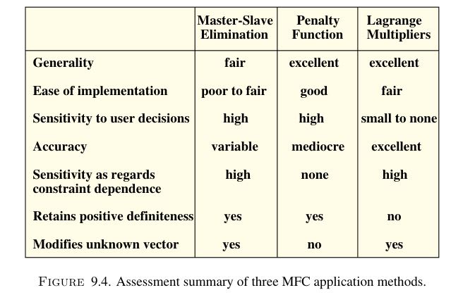
I'm not intimately familiar with how exactly RISA is doing their offsets or P-Delta runs but depending on how either or both are being performed can lead to rapid divergence. Carlos Felippa at University of Boulder had a great free PDF document with two chapters on MultiFreedom Constraints that go into some of the common methods for allowing for offsets, currently not able to find it on their site anymore but try googling for "Felippa Introduction to Finite Element Methods"

Here is a snip of the summary table for the three methods:
Capture_ebbtya.jpg
 
Thanks for your thoughts.

Its unfortunate that RISA uses rigid links to create the offset I think. Particularly an Analysis offset. The usual frame of a floor system will have many depths of members, and if you decide to "never" use offsets then you are agreeing that your members will have different top elevations. It seems RISA could just as easily imply a node (hidden the same way it hides the rigid link currently) at the offset beam centroid location and avoid the link altogether.

I suppose having floor steel with varying TOS elevations is ok, OCD reaction not withstanding, because in reality the 4,6,8,12... inch difference in Centroid connections to the support member probably will not cause deviation from true force redistribution. I have recently been using offsets extensively, because my recent designs are retrofits over, under, and into existing steel frames and I considered it important to try to match the geometry so steel wasn't criss-crossing each other in the model. But having noticed the lower design moment in a beam yesterday because of a rigid link induced moment, I think I am now leaning to "never use".
 
Really the only way to create an offset is with a rigid link, it is either done as an independent link element or via a static condensation of the members stiffness matrix and end force vector to account for the offset (See Matrix Analysis of Structures by Kassimali or Matrix Analysis of Framed Structures by Weaver and Gere for static condensation examples).

the "problem" with offsets/rigid links is in their response to either supporting or supported member deformations and the resulting forces generated by that rigidity. A quick example to see the effect is a single span beam with pinned support each end (rotations free and translations restrained) and an offset applied so that the supports are at the bottom of the beam. The support being at the bottom of the beam will in effect restrain the cross-section rotation so the results will end up very nearly matching a fixed-fixed beam.
 
JT-1995 said:
Its unfortunate that RISA uses rigid links to create the offset I think. Particularly an Analysis offset. The usual frame of a floor system will have many depths of members, and if you decide to "never" use offsets then you are agreeing that your members will have different top elevations. It seems RISA could just as easily imply a node (hidden the same way it hides the rigid link currently) at the offset beam centroid location and avoid the link altogether.

I believe the rigid links are doing exactly what you ASKED them to do. Personally, I think the problem is entirely on your end. You don't understand the concept of rigid links enough to use them properly. That sounds harsh, but that's (IMO) probably true. Have you ever tried to use similar offsets in another structural analysis program? I'm almost certain that you'll get similar results.

FWIW, I just downloaded the reference Celt linked to and I'm excited to read the chapters he referred to. Maybe it's possible that there is a better way to do this that I don't know about. The people who work for RISA are certainly less "academically" knowledgeable about FEM than most companies. So, they (IMO) tend to implement their features (P-Delta, Rigid Diaphragms and such) in ways that are less technically challenging. That's not necessarily a bad thing as they usually do a lot of validation / testing of their features. But, it does mean that they may not know of better ways to do them.

Now, the use of rigid end offsets (using rigid links internally) to model the rigid portion of a beam to column connection is very, very robust. All the engineer wants is to make the portion of the beam that overlaps with the column to be more rigid. And, that's exactly what the offset does.

The problem is when you start treating an analysis program like a CADD program and want to get a rendering that looks as close as possible to what the floor system will look like. What I mean by this is you want to use rigid vertical offsets because you like the way they look. Rather than you want to change the analysis results in some way. Then you get your results and start to wonder why your member results aren't showing the simple beam behavior you know will occur.... It's because you ASKED the program to do this without having a STRUCTURAL reason why wanted that offset.

Caveat: I worked for RISA for 16 years and was the former VP of Engineering / Tech Support / Training. My time there ended rather poorly. And, I currently work for one of their major competitors. So, my opinions on RISA (especially the way they run their company now) are somewhat biased and should be viewed through that lens.
 
JoshPlumSE said:
The problem is when you start treating an analysis program like a CADD program and want to get a rendering that looks as close as possible to what the floor system will look like.

Wanted to highlight this part as I was certainly guilty of this at one point until I tried to validate model results and even then didn't actually understand offsets/rigid links. In the past 5 or so years I've been slowly teaching myself the direct stiffness method which we only briefly touched on in my undergrad education. For me at least the actual math and implementation of the rigid links it surprisingly intensive.

To reiterate Josh offsets/rigid links should never be used just to make the 3D rendering of the analytical model look "right", they should be used purposefully to capture regions of large stiffness variation or known eccentricities ie the highly confined region of concrete between a slab/beam and column you'd apply a rigid offset to the column for the confined region.
 
I wish I had the proof or reference but I do not. Alas, I attended a presentation sometime last year where I recall a discussion of using end offsets in moment frame beam-column joints and it actually was closer to tested behaviour if you don't use rigid end offsets. The extra flexibility near the connection ended up ballparking panel-zone deformation pretty well. Again, take with a grain of salt, wish I remembered who/when the talk was.
 
Luceid said:
Alas, I attended a presentation sometime last year where I recall a discussion of using end offsets in moment frame beam-column joints and it actually was closer to tested behaviour if you don't use rigid end offsets

Yeah, most discussions on Panel Zone shear deformation in STEEL moment frames will touch on this.

Where rigid end offsets really come into play is for CONCRETE moment frames. Especially when you're worried about controlling drift. Also, when you've got the Side Plate type of moment connections which tend to be more rigid than a regular steel connection.
 
Status
Not open for further replies.
Back
Top