Continue to Site

Eng-Tips is the largest engineering community on the Internet

Intelligent Work Forums for Engineering Professionals

  • Congratulations Danlap on being selected by the Eng-Tips community for having the most helpful posts in the forums last week. Way to Go!

Robodrill issues 3

Dbrock11

Mechanical
Oct 28, 2024
9
Drilling two thru holes issues with perpendicularity, same spindle speed and feed all for all holes, but having issues with 1 or 2 holes being misaligned?
 
Replies continue below

Recommended for you

So we drill parts that have a 15 mm gap between the 2 surfaces however when drilling we have misalignment issues when going from one hole to the next hole
 
What support do the two surfaces have - are they deflecting under the force of the drill?
 
Screenshot 2025-01-31 131601.png

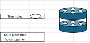
Just remember 2 of the 4 holes are always good. Feeds and speeds always the same. So I'm running into issues with perpendicularity, from one hole to another. There is a interior clamp and one on the top of the part. this is just a quick drawing that doesn't show the inside ID this part has or where the clamps would be on the top of part. also if its deflecting why only certain holes not all if everything is the same?
 
Last edited:
The simple answer is that conditions for drilling two of the hole pairs are not the same as for drilling the other two hole pairs.

It could be a lubricant flow difference, a different drill cycle, some asymmetrical deflection in the part or a fixture.

There is unlikely to be a Fanuc instruction that says "Make random holes incorrectly."
"There is unlikely to be a Fanuc instruction that says "Make random holes incorrectly."

Thanks I needed the aerospace expertise for that.
 
I'm picturing the fixture supports the pieces at two opposing locations, as shown in the sketch.
The upper piece rotates slightly when the drilling force is applied to the holes at 12:00 and 6:00.
Thus the perpendicularity of those holes in the upper piece would not be as good as the holes at 3 and 9.
Is that what you are finding?

 
Since the issue was described as a "robodrill" issue, rather than a drilling issue, the only choices are the Robodrill is mechanically incapable or the Robodrill software has a setting to drill them correctly.

Given that all of the important details that are left out, it's difficult to say what the problem is.

Are they 5 inch deep holes that are 0.0001 inch diameter?
Are they on opposite sides of a piece that is thick aluminum over a foam core?
Is the part configured exactly like you say?
Is the lack of perpendicularity 0.00000001 inch or is it .1 inch
Where is a picture of the item in the machine?
Where is a video of the drilling and all other operations?
Where is a diagram of the fixture?
Are these the first two holes, the last two holes; are these the only 4 holes?
Is there a tool change that uses a different drill for 2 of the holes?
Is there a chance that two holes are drilled complete then a profiling operation shoves the layers out of alignment and then the other two holes are drilled, but the one layer slides back?
What does the tool path look like?

You are asking for a diagnosis on a problem only you have access to information about and you cannot figure it out - yeah. You need aerospace expertise to at least be able to describe the problem in a way that any one else has the slightest chance to look over your shoulder and see what you are currently missing.
 
"Solid piece that holds together" - is this a tubular part (i.e. extends all around the part's circumferences? Or a two-place part like shown? If the latter, I could see that drilling the two off-axis holes might cause the fixture to deflect more, compared to the holes in-line with the solid pieces.

Similarly, is there an axis of alignment for whatever clamps and holds the two parts, and what measures are taken to keep the parts from rotating with the drilling torque applied.

A picture of the fixture with parts loaded might be helpful, or drawings, or video.
 
1739886824499.png
This is the setup it's the small holes that have the issues, current estup has overhead clamps and collet clamping.
 
Ok, I might be misinterpreting what I'm looking at (maybe some red arrows pointing to the "small holes" would help me figure out what I'm looking at). But, always ready to make assumptions: you're drilling holes thru the circular stepped features (or plugs?) on the inner circumference? I could see how mis-spotting the holes could cause the drill to bend if using a single long drill bit for the whole process. Using a short drill (like a center drill) to make the upper hole, then following with a second, longer bit to hit the lower hole, might reduce the error.
 
Correct, however this uses drill and a reamer, I've tried to spot drill to counter for if it's flexing didn't help. Here is a better visual 4 small holes1739902581676.png
 
The video doesn't make sense to the words that you are writing. I thought I knew which four holes you were talking about, but the video shows the drill drilling on the far side of the clamp on the right-hand side of the video frame totally away from the hub of that part, which is nowhere near the four holes that I thought you were talking about, and then the video zooms in while drilling so that I can't see the workpiece. Try again ... or maybe circle in red the exact holes you are talking about and which ones are misaligned with what.

There are two things I don't like.

One, your drill bit is really long and unsupported.

Two, on the four holes that I thought you were talking about, which is the four closely spaced to the central big hole in the illustration in post #13, I don't like the (machined? cast-in?) features surrounding those holes, because those are begging to catch a flute of the drill bit randomly as you plunge in, and send that long drill bit off course.
 
Apologies updated.
This is just the reamer can't send the whole drilling cycle, but I'm noticing perpendicularity and undersize issues and its only these 2 holes you see the drilling on.
 

Attachments

  • Recording 2025-02-19 112634.mp4
    2.6 MB
Brian, we are still in the dark about the scale of the problem and so far there isn't any evidence of a unique difference between the processing of the two hole pairs that are always acceptable and the other two hole pairs that are apparently often rejected.

When someone says "We do exactly the same thing and get different results," it is clear that they aren't doing exactly the same thing each time.

I would change the program to alter the order in which the holes were drilled to see if it followed the holes or the order and I would actually look at the program to see if the operations are in the correct places. Typical debugging steps for any automation failure.
 
Hunh. Same drill as the other holes, but these two holes are the last in the cycle? I'd have said thermal growth, but that's a ton of coolant, so unlikely. I too don't like the indents, and those could cause the drill to wander, but you said you've tried spotting those with a shorter drill bit, and no help? How about drilling through with a short (stub) drill bit, then sending the long drill for the bottom pair of holes? Do similar indent features exist on the upward face of the lower plate being drilled? How much material is the reamer taking off vs. the drill, and what kind of force do you expect for each...i.e. could you 3-step the process to get less force during the drilling and reaming, and maybe reduce the deflection of the part (assuming it's deflection causing the problem). Or try a slower advance?

edit: and thanks for the updates, pix and videos, that helps it become more clear. One more question, looking back at the photo posted yesterday, are there places where the drill sees metal (one on the visible top surface, and one on the lower part, but is there a hole going through the base of the pie-shaped standoff parts? Or are those pie-shaped pieces (kinda looks like a 4-jaw lathe chuck) solid all the way down to the plate of the 2nd part?
 
Last edited:
If the formed dimples are not the same from part to part, and cause the drill point to drift, then would spot-facing that feature first help? Dunno, spitballing ideas here.
 

Part and Inventory Search

Sponsor