Continue to Site

Eng-Tips is the largest engineering community on the Internet

Intelligent Work Forums for Engineering Professionals

  • Congratulations pierreick on being selected by the Eng-Tips community for having the most helpful posts in the forums last week. Way to Go!

Roof hip 1

Henry94606

Student
May 24, 2021
13
Hi structure engineers,
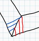
I ve been told roof hip carries half the load of supported rafters.
As in this pix, I can see it carries half the load of red rafters, and other half of the blue rafters, approximately. So, correct if I m wrong, half and half is one.
By geometry, it seems the hip transfers some load to its bottom end (wall corner).

Observation from reality: A) normally I see engineer specify no support at wall corner. Is this load small enough to disregard ?
B) very much a double 2x6 is what I normally see for hip spanning less than 10ft. Is it also the result of the "half load" calculation I am talking about?
Thx
 

Attachments

  • Screenshot_20250203_163411.jpg
    Screenshot_20250203_163411.jpg
    74.1 KB · Views: 2
Replies continue below

Recommended for you

Most hips in typical residential construction aren't designed as beams but rather used a nailers with opposing rafters in compression (similar to the ridge nailer). Valley beams on the other hand are typically designed as beams.
 
Most hips in typical residential construction aren't designed as beams but rather used a nailers with opposing rafters in compression (similar to the ridge nailer). Valley beams on the other hand are typically designed as beams.
Hmm, I design both as beams unless all the rafters come down to a sheathed floor.
To answer the OP's question, for a 45 deg. (in plan) hip, it is a triangular load distribution. The maximum being 1/2 the span of each longest rafter x load x Cos 45 deg. The minimum being zero.
 
Most stud wall corners end up having 3 studs to create the corner and provide appropriate studs to fasten wall finishes to. So maybe that's why there's not a discreet column put in the corner.

From a building envelope perspective, a solid column at the corner poses insulation issues unless all the insulation is outboard rigid, which in my experience is rare in those types of buildings.
 
I would also design this as a beam (not like a nailer). When these members get long I usually see a roof brace coming down to an interior wall somewhere that effectively reduces the span and allows the member size to stay relatively small.
 
It all depends on the overall geometry of the roof. In a symmetrical hip roof of reasonable spans and adequate rafter ties in the long direction tying the end hips together, then the hip need only be a nailer. If the roof is not symmetrical (imbalanced forces) or not adequately tied, then it needs to be designed as a beam. Though, as jayrod mentioned, the corner usually has enough meat in there to support most common conditions by nature of typical construction.

Your sketch looks like you have a flat area on the top of the roof. In that case, it needs to beam.

One thing to note is that the depth should match or exceed the rafters framing into it. Also, it needs a support at the top of the hip regardless of whether not it's been designed as a beam or a nailer. So unless your double 2x6 is supporting 2x4 rafters, it probably violates code.

R802.4.3 Hips and valleys.​

Hip and valley rafters shall be not less than 2 inches (51 mm) nominal in thickness and not less in depth than the cut end of the rafter. Hip and valley rafters shall be supported at the ridge by a brace to a bearing partition or be designed to carry and distribute the specific load at that point.
 
Hmm, I design both as beams unless all the rafters come down to a sheathed floor.
To answer the OP's question, for a 45 deg. (in plan) hip, it is a triangular load distribution. The maximum being 1/2 the span of each longest rafter x load x Cos 45 deg. The minimum being zero.

Thank you.
I guess the rule of thumb "hip carries half the load" came from old timers when paper and pencils were still used.
My old drafting technique always draw hip roof at 45° line, which yield its cosin value to 0.7, from your math. If so the rule of thumb at least should be "three quarter of the load" not "half".
 
If so the rule of thumb at least should be "three quarter of the load" not "half".
No, I think you're getting a few things mixed up here.

"hip carries half the load" is in fact accurate.

The cos45 factor mentioned by XR250 which is (0.707) or 1/sqrt(2) is being applied to the triangular load distribution because the hip is skewed at a 45 degree angle relative to the rafters. In other words, the distance between rafters along the hip is greater than the rafter spacing. In this case, if the rafters were spaced at 12" o.c., they would be spaced about 17" apart along the hip. That's where this factor comes in. I've seen this get screwed up a million times in beam calculations.

You can check your beam loading by taking the sum of the two end reactions and comparing that to the total load applied to the area of the red and blue rafters. It should be half of that. If it's not, you probably missed that factor.
 
Thank you all for your taking the time responding to this post.
It s obvious I am not an engineer (I am an architect) learning piece by piece from this valuable forum.
This post teaches me:
1) the cosine adjustment value is referred to the slope of the hip.
2) both the hip or valley should be treated as beam, to be safe.
Thx
 

Part and Inventory Search

Sponsor