Continue to Site

Eng-Tips is the largest engineering community on the Internet

Intelligent Work Forums for Engineering Professionals

  • Congratulations KootK on being selected by the Eng-Tips community for having the most helpful posts in the forums last week. Way to Go!

Roof Load Path?

Status
Not open for further replies.

Redacted

Structural
Mar 12, 2016
160
Hi there,

I'd like to confirm my understanding of a typical hip roof load path (compression roof).

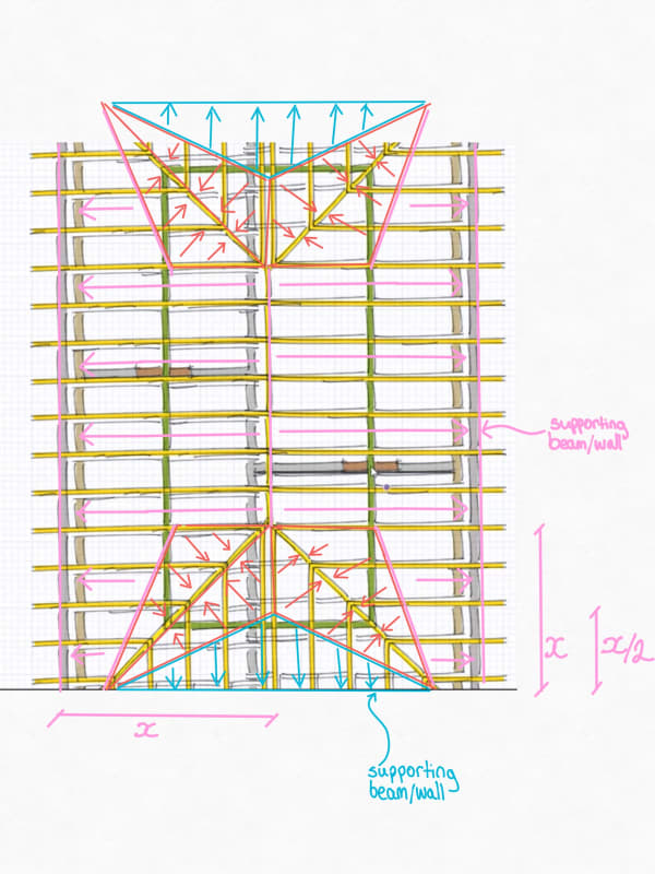
Are my load path assumptions in the sketch below correct?

Mainly interested in the load share between the hip rafters/supporting wall and the ridge board (compression)/supporting wall.

I'm working on calculating the roof load on the supporting wall/beams.

New_Drawing_17_-_Copy_w2k5ga.jpg


Is there any good literature/books on load paths for buildings that goes into stuff like this in detail?
 
Replies continue below

Recommended for you

By "compression roof", I assume you mean the bottom of the rafters are connected to a floor/ceiling diaphragm in such a way that the outward thrust of the rafters under gravity load is resisted. This would be similar to a trussed roof.

If that's true, then I think the loads you're calculating going to the supporting walls are half of what they should be. For a "compression roof", there should be no vertical load going to the ridge or the hips. If there is, then you should be designing structural ridge and hip beams for that load.

Your loading would be accurate if you did not have a "compression roof" and were relying on structural ridge and hip beams.

I can't think of any literature that goes into this off the top of my head. I'm sure there must be though.
 
Thanks for the response Eng16080, it's very helpful!

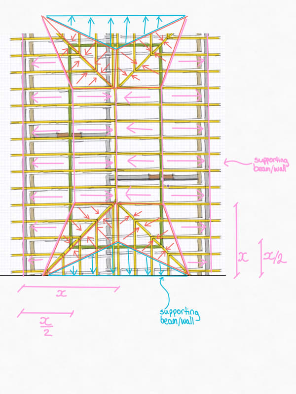
Correct, this roof will have the rafters connect with a ridge board at the apex and have a timber tie to resist outward thrust under the gravity loads. So that makes sense to me that this will act as a truss (e.g. vertical load reactions will be at the supporting walls). I've double the main rafter tributary area acting on the wall.

New_Drawing_17_1_-_Copy_ayzbaq.jpg


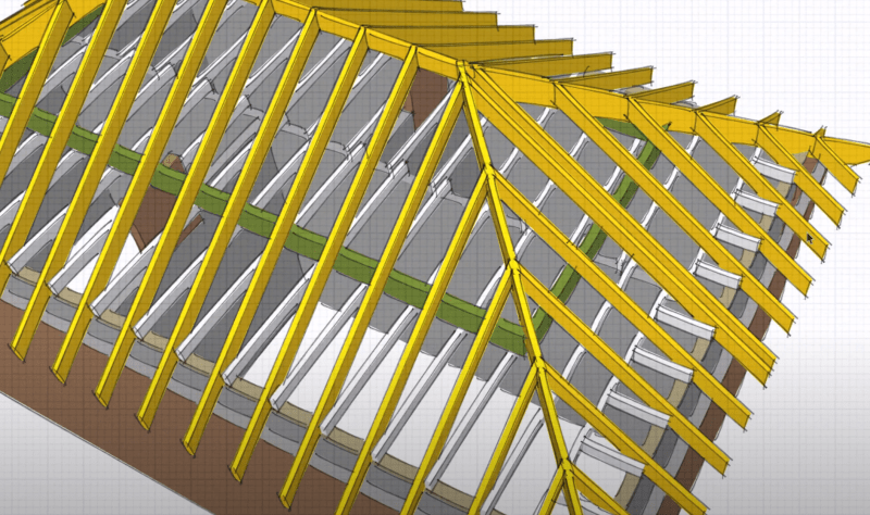
However, I'm still a bit unsure about the tributary area/load path for the hip rafters. The jack rafters will connect to the hip rafter (similar to what's shown below - although that green purlin is not in the roof structure I am looking at) and there are no timber ties like with the main rafters. Although I should note that the hip/jack rafters will tie into a timber wall plate anchored to a bond beam on top of the wall to resist outward thrust.

In this case should the load path assumption be that the hip rafters were designed as a beam to take the load (I didn't design this roof, only designing a new beam for an opening in one of the supporting walls).

As the ridge board isn't structural, I'm assuming that the apex of the hip rafters (where they meet) would need to have the same equal/opposite forces, and all vertical load in the hip rafter will need to be taken down to the wall supports. Is this the case?

ridge_rafters_-_Copy_wvnrzs.png
 
That's a good question. I don't think there would really be any vertical load to the hips. The way I think about this is that the bottom of the rafters (including the jack rafters) are essentially pinned. Considering the bottom as pinned, then any given rafter will be stable as long as a horizontal force at the top of the rafter can be resisted. I imagine that a ladder is resting up against a wall made of ice and the bottom of the ladder is connected to the floor with a hinge (pinned connection). At the top of the ladder, the wall can't resist any vertical load but it will resist a horizontal load. This is how I think of the rafters in a "compression roof." [While on the topic, if the bottom of the rafters are not connected to the floor/ceiling, then I think of this in a similar manner except with the bottom of the ladder not connected to the floor (which is also ice). Then the bottom of the ladder can slide horizontally. In this case, it becomes obvious that the ladder will be unstable unless there's a vertical support at the top (like a structural ridge beam).]

So, then the question is whether or not a horizontal force can be resisted at the top of the jack rafters. I think the answer would probably be yes assuming that you have a roof diaphragm (plywood nailed to the rafters). Even without relying on a roof diaphragm, though, it's possible that the roof would still work. I think you would find that the ridge and hip boards all act as compression members if you were to analyze a 3D model of this, and that the size of those members to work by code would be reasonable.

One other observation is that for a roof like this to fail globally, even without any horizontal support at the bottom of the rafters, the roof sheathing would have to either rip apart or detach from the hips to fail. I'm not sure that's of much use in analyzing this, but I think it's the reason why a lot of roofs which seem wildly inadequate based on analysis can often hold-up in the real world. As an engineer, though, I wouldn't want to rely on the strength of the sheathing in the case of no horizontal support at the bottom.

Finally, I think the actual distribution of forces and stresses in a roof like this is some complicated interaction between the framing members, roof sheathing, and nails. If you're not certain of what's going on, I would probably create a 3D model in RISA 3D or some other software as a sanity check. You would just model the framing members and wouldn't account for any additional strength from the plywood (aside from bracing the members against buckling).
 
I had no idea people still build like this. Wouldn't it be much cheaper to just specify roof trusses?
 
Concerning using roof trusses for this, I assume that they:
1. Either want the floor/ceiling space to be open, or
2. Consider "stick framing" or "field framing" more cost effective.

In general, if having an open floor/ceiling space is not a concern, around where I work, trusses are usually most economical. Some builders, though, just don't like to use prefab. trusses due to the extra coordination. I've also had builders who weren't that busy (not recently though) and would rather pay their framers to build the roof rather than giving their money to the truss supplier, even if it was a little cheaper.
 
Do not waste your lime on a 3-D model. This is how most roofs are framed in my area minus the green supporting wall as usually the roofs are 34 ft wide max. so the rafters do not need additional support.
I design these with the hips as beams supported down to a wall or ceiling beam. The support does not have to be all the way at the top of the hip as it can cantilever a bit. Also if the roof is small enough, I usually just double up the rafter and ceiling joist at the peak of the hip and use that as a truss to provide the support. If the attic floor is completely sheathed, I usually consider the hips just nailers and not beams.
 
XR250 said:
Do not waste your lime on a 3-D model.
I was suggesting this as a way to get a better understanding of how the structure works in this situation, not something that you would do for every like project.

XR250 said:
If the attic floor is completely sheathed, I usually consider the hips just nailers and not beams.
I think we agree on this.
 
Status
Not open for further replies.

Part and Inventory Search

Sponsor