Continue to Site

Eng-Tips is the largest engineering community on the Internet

Intelligent Work Forums for Engineering Professionals

  • Congratulations SSS148 on being selected by the Eng-Tips community for having the most helpful posts in the forums last week. Way to Go!

roof plane bracing - forces?

Status
Not open for further replies.

mats12

Geotechnical
Dec 17, 2016
181
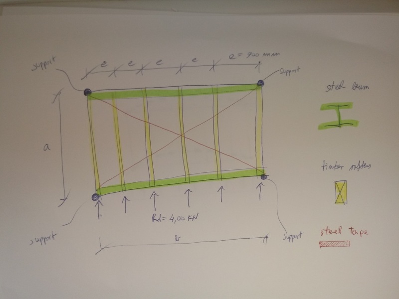
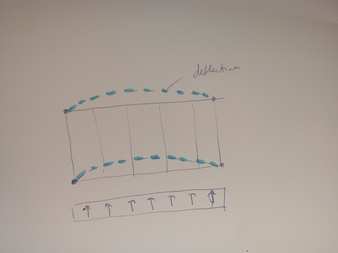
Hello,I want to avoid horizontal deflection and biaxial bending of steel beams that supports timber rafters. I want to transfer all horizontal load from roof to supporst (longitudinal concrete wall).

I m not allowed to use timber sheating, so Im using steel tapes (I dont know a proper expression in English) which are fixed on every rafter they pass.
Supports are horizontal unmovable. Force is 4 kN per rafter.
How can I calculate tension forces in the steel tape (bracing)?

20170716_193203_lpclaf.jpg


zavetrovanje_trakovi_zsm1lx.png


20170716_193213_t74pku.jpg
 
Replies continue below

Recommended for you

What are you using to deflect rain, provide shade, etc.? Almost anything will do that. The straps also will, but not if the "sheathing" is capable of the job.
 
this is on the rafters: its a thin metal + insulation
i dont think that can be considered as sheating...


tr_inptkj.png
 
In this particular case, if (b >> a), then steel straps will be inefficient. I bet your steel beam is stiffer. If you want to use straps, don't connect just your supports with it - go from support to the middle of the steel beam - in all directions of course. Then do analysis as a truss to get forces in straps.
 
Mats12 said:
this is on the rafters: its a thin metal + insulation
i dont think that can be considered as sheating...
If it has metal on the bottom you may be able to use it. What is the gage?
 
I'd check with the supplier and ask about other installations. My money wold be on the result that those other sites have no problem with this roofing provided it is nailed on every rafter and at each "ridge".
 
back to your question.... if each rafter loads a tension strap then each strap is taking 1/2 of all rafters. so N*4kn *0.5. Then convert that force into components. your rafter needs to handle the weak axis (or blocking) and the strap gets rest.

Unless i misunderstand your intention
 
@EngineeringEric, the straps only work in tension, so wouldn't each connection take the full force?

Either way if your force is 4 KN per rafters your not getting that w/ nails, and that's not including the component perpendicular to the rafters you need to resist at the end of the strap. I guess if you had blocking between the rafters periodicsly, which it looks like you will need to support the metal panel that will be spanning g parallel to the rafters, you could reason that the compression force perpendicular to the rafters would be resolved through that. If it was me I would either design the top flange of the beam to span out of plane or tell them they are not allowed to build a roof structure without a functioning diaphram. That is unless the manufacturer has published shear values and connections for their panels.
 
I don't understand your sketch ...

1) is the surface shown supported on four sides or two ?

2) as drawn are the steel beams bending (significantly) or working as caps (ie one in tension, one in compression) and isn't there a sheathing web to carry the in-plane shear ?

another day in paradise, or is paradise one day closer ?
 
What's the issue with designing the beam for biaxial bending?
You could carry half the horizontal load in each beam.

If deflection is not a huge issue for the facade/building just design for strength and call it a day!
 
Status
Not open for further replies.

Part and Inventory Search

Sponsor