Continue to Site

Eng-Tips is the largest engineering community on the Internet

Intelligent Work Forums for Engineering Professionals

  • Congratulations KootK on being selected by the Eng-Tips community for having the most helpful posts in the forums last week. Way to Go!

Roof Plywood Nails - Wind Tension & Shear Interaction question

Status
Not open for further replies.

structuresguy

Structural
Apr 10, 2003
505
A question has come up on how to design nailing patterns for roof plywoood, considering combined interaction of uplift loads and diaphragm shear. I have typically done a linear interaction of tension/shear for fasteners, but can't find any direct language to this interaction for engineered panels. Basically, if I use the APA tables for allowable horizontal diaphragm nailing, and want to also consider nail withdrawal for simutaneous uplift loads, what is the best way to calculate this interaction? There is an equation in NDS for interaction with nails, but it is based on individual nail capacities, not engineered panel capacities.

So I am thinking to calculate the number of nails in a 4x8 sheet of plywood, based on the diaphragm capacity tables, then work out the total uplift on that 4x8 sheet, then using the withdrawal capacity of each nail, calculate the total allowable uplift load based on the number of nails. Then I could do a linear (or otherwise) interaction of the withdrawal tension and diaphragm shear. This is the same approach we use for metal deck fastening patterns. What do you think?

Thanks very much.
 
Replies continue below

Recommended for you

I don't mean to sound flippant or lazy, but I don't think anyone ever checks this.

DaveAtkins
 
Good question, I have thought about this when dealing with steel deck where there are tables and published info for this, but I don't ever remember reading anything similar for nails and plywood.

I don't know this as fact, but I would assume the failure mode in uplift and shear would be localized failure of the plywood in pullover action. Shear forces would cause localized crushing of the wood and bend the nail, and uplift and shear forces would combine and ultimate cause a pullover failure.

I think the practical way to handle it is design your diaphragm for shear and get your nailing schedule. Figure out how much uplift force you have PER NAIL, and compare that with your shear capacity, using an interaction equation or just engineering judgment. Then either just increase your nailing schedule for the whole building or in zones of higher uplift. But using common sense, when a guy is slinging plywood on a hot summer day and he is just going crazy with a nail gun, just use more nails instead of an overly complicated nail schedule that they probably won't read or understand anyway. I figured this out after inspecting my first big wood framed job right out of college and I just saw nails and straps everywhere and talked to a couple of framers. I realized just go with more nails was way easier than overly-complicated schedules.

Unless it is a huge, rectangular box or something easy to show on a diagram (I am thinking of chopped up, overly complicated hip roofs on custom houses).
 
I wonder if the shear would enhance the pullout of capacity of the nail?
 
XR250....In my opinion, shear reduces the pullout capacity of nails...think of it this way....shear pushes the nail against one side of its hole, while pulling it away from the other side. The increased friction resistance on the "pushed" side does not likely equal the loss of friction on the "pulled" side, yet the face areas are essentially the same...thus reduction in pullout.

Hey KootK....let's debate this one![lol]

Dave....I agree! Overanalysis!
 
Ron said:
Hey KootK....let's debate this one!lol

What the heck Ron? Were you somehow able to sense me lurking in the background? I totally was. Unfortunately, I've got nothing to contribute on this one other than my general disdain for the absence of an accepted design procedure for combined loading. For wind loads, cases where maximum diaphragm demands are present are quite likely to occur simultaneously with significant uplift.

I like to debate structural engineering theory -- a lot. If I challenge you on something, know that I'm doing so because I respect your opinion enough to either change it or adopt it.
 
@Ron;

I guess we could also think that the shear would tend to cock the nail in the rafter - increasing the force at the top and bottom (on opposite sides) and reducing it on the others sides.
Probably reduces the friction overall as you said, however.

I'll stick with just ignoring the whole subject
 
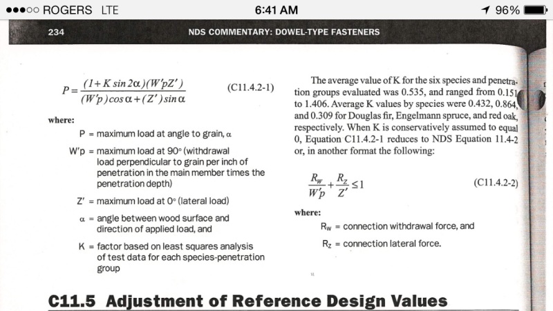
For reference, the non-engineered panel interaction equation is shown below (2005 NDS). Two additional complicating factors:

1) In a blocked panel, only the 4x8 sheet perimeter nails are loaded in shear. The interior nails should be 100% available for withdrawal. Well, almost. The interior nails are needed to prevent shear buckling within individual plywood sheets. That buckling prevention itself would induce withdrawal loads. I'll wager this are small loads however.

2) In an unblocked diaphragm, shear transfer between two of sheets is rather complex and would involve some of the interior nails. Frankly, I wouldn't know how to calculate the shear per nail in an unblocked diaphragm without veering way off into "making stuff up" territory.

image_sxbrrd.jpg


I like to debate structural engineering theory -- a lot. If I challenge you on something, know that I'm doing so because I respect your opinion enough to either change it or adopt it.
 
Sorry for being absent since i posted this question. But it is very interesting to see that there is clearly no accepted approach to this problem. I also reached out to APA, and their engineer replied that they had never been asked this question before (paraphrasing), and suggested that they be considered separately due to perimeter nails taking mainly shear and field nails taking mainly uplift. I guess I don't completely disagree with this approach. It should be easy enough to assume shear taken only by perimeter nails, then work out the uplift trib for those nails, and then use the interaction equations in NDS for the individual nails. If you started from an engineered panel nailing pattern, and the interaction on the nails still worked out, I guess it should work. I'm just dissappointed that there isn't a recommended approach, similar to metal deck fastening interaction equations published by the SDI.

Thanks for your thoughts.
 
I think the advice that "perimeter nails taking mainly shear and field nails taking mainly uplift" is ignorant. When a roof deck lifts off, it starts at the edges.
 
True enough. Clearly, all the nails in a sheet of plywood will contribute to both. However, along the perimeter edge of the sheet, the trib for uplift is much less than in the field of the sheet, just due to the nail spacing. So the uplift force on the edge nails will be less than the nails in the field. Conversely, the shear in the field nails will be less than along the edges. So my thought was to assume that the shear is taken only by the edge nails, which should be a conservative assumption. Then using the uplift trib on those edge nails, work out the withdrawal force. Then using an shear-withdrawal interaction (linear or otherwise), check the adequacy of the nails for the combined loads, with the nail spacing based on a diaphragm shear capacity table.

So as an example, say we have a diaphragm capacity of 360 plf with 8d nails @ 4" o.c. along edges and 12" o.c. in the field. Now say we have an actual diaphragm load of 240 plf, and an uplift pressure of 100 psf. So we have the following:

n = 12" / 4" = 3 nails per ft along edges

V = 360 plf / 3 = 120 lb / nail
V_allow = 1.6 * 83 lb = 133 lb (1.6 for wind factor and 83 lb per NDS)

Tributary area = 4" * 12" = 0.33 SF for edge nails with supports @ 24" o.c.

T = 0.33 sf * 100 psf = 33 lb
T_allow = 1.6 * 1.875" * 41 lb/in = 123 lb (for wind per NDS with 5/8" plywood)

Liner interaction:

T / T_allow + V / V_allow <= 1.0

33/123 + 120/133 = 0.27 + 0.90 = 1.17 > 1.0 thus no good.

5/3 interaction:

(33/123)^5/3 + (120/133)^5/3 = 0.11 + 0.84 = 0.95 thus OK.

So now the question is what type of interaction: linear, 5/3, squared

For metal deck I use linear, but for post installed anchors into concrete, most manufacturers recommend 5/3 interaction. I am inclined to use linear for nails into wood.
 
I'd stick with linear interaction, similar to what Koot showed in his phone screenshot from NDS. There's significant testing on concrete interaction to warrant the parabolic interaction.

On another note, this is a very good thread and I'm glad this topic was brought up. Thanks to the OP!
 
A couple of things worth mentioning perhaps:

1) In my opinion, there truly will be no shear transfer through the interior nails unless the panel picks up additional, secondary shear from framing attached to the interior of the panel. This would be the case, say, if the plywood sheet were attached to roof trusses resisting wall lateral loads. I expect these secondary shears would be minor.

2) While uplift may initiate at the panel edges, I think that one could still make an argument for resisting uplift with the interior fastening only. Presumably, edge nails would fail in combined shear and withdrawal by withdrawing. The withdrawal would be self limiting, however, as panel flexure would soon transfer the uplift to the interior fasteners. I expect that shear capacity of the nails would be only marginally affected by the slight withdrawal. Following this logic, the first interior nails would need to resist an uplift force associated with a tributary width of 1.5 x framing spacing.

I like to debate structural engineering theory -- a lot. If I challenge you on something, know that I'm doing so because I respect your opinion enough to either change it or adopt it.
 
Roof's have about half the wind shear as a floor because it has half trib width. you're gonna use the same nail spacing throughout (well, we always do). So the nails on the roof have additional uplift load but half the design shear.

Let's say 1/2" thick sheathing and a 6d nail. Framing members are SYP No. 2. Withdrawal = 1380*G^(5/2)*D = 1380*(0.55)^2.5 *0.113in = 35 lb/in

Cd = 1.6 for wind and a 6d nail is 2in long, so 1.5in into main member. 1.6*35lb/in *1.5in = 84# per nail uplift capacity

field nails are 12" OC. so if framing is 24" OC for a roof, we have 9 field nails? if we only count on them, we'd need 9*84# / 32ft^2 = 23psf ASD uplift which isn't very high at all. hmmm i would use all the nails for uplift.
 
My comment about wind uplift is for exposed edges, where the pressure is much higher than in the interior. Each fastener sees more tension if the spacing remains the same.
 
Status
Not open for further replies.

Part and Inventory Search

Sponsor