Continue to Site

Eng-Tips is the largest engineering community on the Internet

Intelligent Work Forums for Engineering Professionals

  • Congratulations Danlap on being selected by the Eng-Tips community for having the most helpful posts in the forums last week. Way to Go!

Roofing Fastening Detail - Loads and General Critique 2

KootK

Structural
Oct 16, 2001
18,322
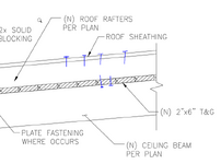
I'm hoping to evaluate the uplift capacity on the re-roofing detail shown below. I don't have a great depth of experience in this space and could use some bounce. Feel free to answer any of the questions below with no obligation to answer them all. US / Canadian / Other Places answers welcome. This is Canadian work FWIW.

1) Other than testing, how does one go about calculating uplift loads on roofing? This is related to a recent thread by @bookowski: Roof Topping Slab in High Wind.

2) Should I be worried about screws hitting the T&G joints?

3) Is there a way to install this and avoid hitting the T&G joints with the screws?

4) Do I have to satisfy that NDS thing where connections have to extend at least to the centroid of the supporting thing (deck boards)? That could get tight for tolerances on a 1.5" thick substrate. Obviously, it won't be cool if the screws are sticking out into the interior space below. The soffit is exposed.

5) Is this a generally sketchy setup?

6) Got any better / more conventional ideas? We're exploring adhered but not loving that on a pitched roof.
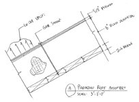
c01.JPG
 
Replies continue below

Recommended for you

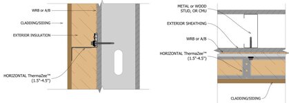
Would a pattern of cold-formed Z sections work, assume would need to be discontinuous for energy, then you could do the shorter Simpson #6X1/2" screws or deeper if needed installed before the insulation making it easy to miss the joints and then whatever fastener you want for the plywood to Z attachment.
 
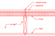
i think that the screws or nails shall be to the roof rafters by pywood top and bottom to T&G whith depth of rafter 10" min. 1739475565821.png
 
Would a pattern of cold-formed Z sections work, assume would need to be discontinuous for energy...

That's got curb appeal. Any idea how one goes about making it discontinuous?
 
was thinking discontinuous in plan rather than through the depth, so maybe something like 24" long @ 4 ft o.c.
 
I like Celt's idea, though foam insulation may be needed to make it work.

1739476101203.png
 
was thinking discontinuous in plan rather than through the depth, so maybe something like 24" long @ 4 ft o.c.

That would not seem to solve the thermal break thing. What am I missing. There's a specialty product online but it tops out at 4.5".

c01.JPG
 
I like Celt's idea, though foam insulation may be needed to make it work.

Is that really something that can be done? Screw through the insulation and self tap into a sheet metal flange below? I'm game if it's possible. I've just never seen it done.
 
Last edited:
For loading, I guess you could use the Canadian equivalent for ASCE 7's Components & Cladding loads (if that's a thing). I feel like that could be over kill, but it would be conservative. Looking at the thread you linked, it seems like they were trying to work with a fairly extreme edge case. IIRC the C&C for pitch roofs tends to not get too crazy because it's easier for the wind to roll over.

Is that really something that can be done? Screw through the insulation and self tap into a sheet metal flange below? I'm game if it's possible. I've just never seen it done.
I don't see why not. I haven't seen it done before either, though. The biggest hurdle maybe finding a self taping machine screw for light gauge metal that is long enough to float through the insulation, but at a quick glance the pull out values should be workable depending on your conditions. Wouldn't be a huge fan of this kind of set up if you were putting the screw into a bending, but if uplift is your only concern, I think it makes a lot of sense.

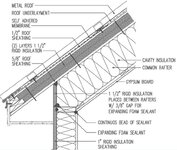
alternatively, maybe something like this?
1739477708924.png
 
Riffing of of the detail below, may this is the way to go. Two layers of sheathing with the lowest being connected to the deck boards.

c01.JPG
 
Is that really something that can be done? Screw through the insulation and self tap into a sheet metal flange below? I'm game if it's possible. I've just never seen it done.
I've never seen it either, but I don't see why not. Your original design is screwing through insulation and into a substrate. This just adds an additional substrate. you may end up needed to do a couple of layers, though - spray foam up to the top of the purlins, then rigid over top to give you a smooth surface for your roof protection board.
 
Wouldn't be a huge fan of this kind of set up if you were putting the screw into a bending, but if uplift is your only concern, I think it makes a lot of sense.

Thanks for your contribution @DigiAlmond. With reference to the quoted comment, I've been kind of assuming that we just sort of handwave the tendency for the roofing to shift downslope? I'm sure that rigid insulation is a "ply" in the the NDS connection sense of things. Just a rather difficult one to assess. Probably does a version of strut and tie.
 
Your original design is screwing through insulation and into a substrate. This just adds an additional substrate.

I see your point. With the deck boards as the substrate, that kind of feels like the boards won't try to shift away from the screw like the top flange of a z-girt will. That said, metal roofing gets fastened to z-girts successfully so, clearly, it's possible. Thanks for walking me through it.
 
Thanks for your contribution @DigiAlmond. With reference to the quoted comment, I've been kind of assuming that we just sort of handwave the tendency for the roofing to shift downslope? I'm sure that rigid insulation is a "ply" in the the NDS connection sense of things. Just a rather difficult one to assess. Probably does a version of strut and tie.
That was my assumption. I think if these connections are decently close (which it sounds like they will be) it's probably a wash. But I would probably check with the arch and make sure the insulation on the T&G has some method of attachment to the T&G, for good measure. Doesn't need to be perfect, but it certainly wouldn't hurt to preclude any shifting that might put additional stress on your screws.
 
But I would probably check with the arch and make sure the insulation on the T&G has some method of attachment to the T&G, for good measure.

As in adhering it? Intuitively, I certainly wouldn't relish the thought of wind gusting underneath it. Granted, that would take a fair bit of separation.
 
For loading, I guess you could use the Canadian equivalent for ASCE 7's Components & Cladding loads (if that's a thing).

Yeah, come to think of it is that straight forward. That other thread that I referenced got me turned around on this. But I guess a normal cladding situation is a bit different from a slab topping. I imagine that we assume that the interior pressurization carries through to at least the vapor barrier.
 
Yeah, come to think of it is that straight forward. That other thread that I referenced got me turned around on this. But I guess a normal cladding situation is a bit different from a slab topping. I imagine that we assume that the interior pressurization carries through to at least the vapor barrier.
It's easy to over-think after reading a really good thread like that. I skimmed it and I realized I have a good bit of reading I need to catch up on. But traditionally C&C has been good enough from me in similar situations.

As in adhering it? Intuitively, I certainly wouldn't relish the thought of wind gusting underneath it. Granted, that would take a fair bit of separation.
Yes adhering it or some other way (if they exist). I didn't think of any sort of gust or anything like that, I just meant to negate the effects of it sliding or shifting down the slope over time. Essentially my thought is you may want to ensure your assumption (no/minimal shift) is what ends up actually happens, if you are concerned about any sort of shifting. That seems like the kind of things some engineers might be concerned about and others would think is fine.
 
You might be able to compare to some FM Global Roof Nav assemblies. Not sure what your wind load is but say it’s 45 PSF ULS unfactored, you can copy the fastening of an FM 1-90 roof assembly (failure load of 90 psf).
 
Rigid insulation typically (but not always) gets its own fasteners into the deck. Sometimes an overlying coverboard is needed, as with extruded polystyrene.

NRCA has a manual with good roof details.

Just use C&C wind loads. The air-permeability of each “layer” determines the actual load.
 
KootK:

Take look at these two documents on fastening thick claddings to a wood frame. Link1, Link2 They're from Building Science Corp. The second link shows fastening 10" insulation. The first one is some structural research they did on fastening thick claddings.

Regards
DB

NB: Joe Lstiburek is a paisan of yours. Graduated from U of T.
 

Part and Inventory Search

Sponsor