Eng-Tips is the largest engineering community on the Internet

Intelligent Work Forums for Engineering Professionals

Rotary to linear mechanism calculations- - -Need help!! 1

Status
Not open for further replies.

Vikas4auto2019

Mechanical
Sep 23, 2019
13
0
0
US
hello guys,

PLEASE FIND THE IMAGE BELOW YTO UNDERSTAND MY QUESTION.

Capture_l9mqjo.jpg

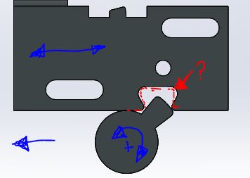
I just wanted to know that.. is there any empirical // calculative method to design the slot for (max) linear motion.
what are the parameters I need to get for these calculations?

Also, let me know what types of motion we can call it.


Thanks in advance. :)
 
Replies continue below

Recommended for you

Yess Greg.. you are correct, I want to find the shape of the socket. for given cam shape (circular part). I want a design method for this.

THANKS IN ADVANCE.
 
Your method has a lot of friction, wear, varying output speed. A rack and pinion, or chain drive, or linkage solves all of those. You can do it your way. Its just that there are other well-established and well-documented options.
 
Thank you all for your suggestions.. @Jboggs in my case I don't have a choice to change in the shape of tooth/ cylindrical part. The slot is the only thins which I can design. :)
 
Google : "Ingenious mechanisms for designers and inventors" vol IV (free download) (Ch 7 reciprocating motions derived from cams, gears and levers = Ch 8 crank actuated reciprocating mechanisms = Ch 9 variable stroke reciprocating mechanisms)
Google : "Mechanisms, linkages and mechanical controls" - Chapter 2 : mechanisms for intermittent, dwell, and reciprocating motion - Nicholas Chironis - McGraw-Hill
 
I like TheTick's idea. Involute gear teeth can be very efficient (>95%). I believe you could treat the driven device as a rack (straight sided teeth) and the cam as a gear tooth (involute profiles for the sides of the cam). You'd necessarily have some backlash on direction reversal.
 
Vikas, if the only geometry you can change is the shape of the slot in the linear piece, then you will have to do it the old fashioned way. the same way that our ancestors did it, and it worked well for them. Pick a shape that you think might work and draw the interface at iterative amounts of rotation from first contact to last, say every 5 or 10 degrees. Be sure you are accounting for every point of contact in every case.
 
For all similar cam drives - you place the linear part in the location you want at the same time you put the rotary part at the rotation angle that is to produce it. Then cut away the linear part that interferes with the rotary part. As long as the motion for this operation is such that material is always removed it will correspond to the cam driving the slot.

This is exactly how actual gears and cams can be produced; a hob of the final section removes material that interferes until the mating part is completed.
 
If you superimpose the images of cam at different parts of its rotation, it carves out its maximum space claim envelope, which is a full circle for full rotation. If the bottom of the moving piece is above the round part of the cam, then the slot only needs to be big enough to engage the cam, and you can get something like the slot positions in yellow. If, not, then some variation of the slot positions in red. In the latter case, the slot is larger to accommodate the round part, but it also means that the total lateral movement is less than the yellow case.

cam_slot_dtngw9.png


TTFN (ta ta for now)
I can do absolutely anything. I'm an expert! faq731-376 forum1529 Entire Forum list
 
Status
Not open for further replies.
Back
Top