Continue to Site

Eng-Tips is the largest engineering community on the Internet

Intelligent Work Forums for Engineering Professionals

  • Congratulations waross on being selected by the Eng-Tips community for having the most helpful posts in the forums last week. Way to Go!

Rotational Assembly

BakerJ92

Industrial
Nov 2, 2024
3
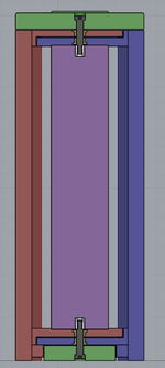
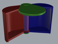
Hello everyone, new to the site and am hopeful that I'll be able to receive some help. I'm not entirely sure my question has to do with mechanical engineering as I do not have any sort of engineering background, but it seemed like the right place to start. By trade I am actually a CNC operator working in furniture manufacturing, which finally leads me to my question. I am trying to design a object that firmly joins three separate components together but also allows for rotational movement around a center point. I am fairly proficient with the modeling software Rhino for those who are familiar with it and have been looking to McMaster Carr for all of the assembly's components. I will attach an image of what I have come up with so far. Essentially the red and blue components are to rotate around the shaft with some bearings that are house inside each of the components with the use of some washers/spaces to give everything a little clearance in the z-axis and fixed in place with some shaft collars. Initially the green component was to rotate freely around the shaft as well with a bearing housed inside but I am not thinking that I might like to have the green component fixed in place with the shaft directly connected to it and only the blue and red components rotate freely.

Again really not sure if this is the place for this question, it seems very basic but I've never had to design anything like this before and could really use some help. I am also genuinely interested in gaining further knowledge about these types of assemblies, utilizing parts sourced from mcmaster that allow objects to become more dynamic. So if anyone wanted to point me towards some resources to do that I would greatly appreciate it!

Thank you for your time!
 

Attachments

  • Screenshot 2024-11-02 at 12.33.55 PM.png
    Screenshot 2024-11-02 at 12.33.55 PM.png
    136.1 KB · Views: 30
Replies continue below

Recommended for you

you need to consider few things such as load to be taken by the components, the speed of rotation, direction of load, materials, etc... physically, I don't see any issue.
 
Not having any real engineering background I’m afraid I do not have the skills to calculate loads. To provide a little more clarity this is a standalone piece of furniture measuring roughly 18” wide x 24” deep x 30” tall that will be constructed primarily out of 1” thick plywood. The left half will rotate to the left and the right half will rotate to the right, both only about 70° in rotation. Nothing will be constantly spinning, moving very fast, or frequent. I do however want everything to operate smoothly.

I have altered my assembly and believe it will show more clearly what I am trying to achieve. I have two main concerns.

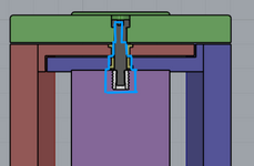
1. The top green section essentially cantilevers 18” off of a 4” this needing quite a rigid connection between the shoulder screw and threaded insert in the post.

2. All of the other components that allow for rotation are sandwiched in between those two points, if the shoulder screw is really torqued down in to that threaded insert will it still allow for the other components to rotate smoothly?Screenshot 2024-11-05 at 7.58.07 AM.png
 
as long as you provide some allowances for all mating parts, they sure will rotate freely. again, it's difficult to decide how much tolerance you need as you can't advice your specific load, etc. but as a hobbyist woodworker, I don't see any issue and I can always fix my mistake when working with wood.
 
Where is the weight of the moving parts transferred to the frame? It looks like the blue part grinds on the lower green support and the red part grinds on the blue part. The purple part seems crushed between them all, tending to lock them all together.
 
I'll provide another angle of the piece that will maybe help display exactly what it is and how it functions. Everything is ultimately kind of "crushed" all together, which is kind of why I'm here, concerned about everything operating smoothly. I do not know that the assembly I have proposed is the best solution it's kind of just the best I could come up with at this time. The assembly is as follows, shoulder screw passes through a series of washers (to provide spacing between the plywood layers) and flanged bushings (recessed into the two halp-lapped cabinet "doors"), and threads into a threaded insert in the main post. There will be a 1/8" aluminium plate (offset inward roughly 1" from the outer profile) that is recessed/laminated into the green top to help provide rigidity for the cantilever and also kind of act as a "washer" for the shoulder screw. In my mind the top is secured firmly through the voids and into the post remaining stationary, while the "doors" rotate on the fixed recessed bushings around the shoulder screw internally but probably rubbing pretty firmly against the washer both above and below. I imagine the connection need to be very rigid so as to not allow the top to sag and the doors butt against the bottom edge as they attempt to come to a close. The allowances I have assigned are 1/16" of an inch (the thickness of all the washers), and those diameters are also 3/4" (smaller than the bushings 1" flanged diameter and equal to the bushings bottom diameter. Screenshot 2024-11-06 at 12.12.26 AM.png
 

Attachments

  • Screenshot 2024-11-06 at 12.29.56 AM.png
    Screenshot 2024-11-06 at 12.29.56 AM.png
    110.8 KB · Views: 4
Last edited:
You need thrust bearings between the colors.

That might be as simple as plastic or bronze washers if the loads and speeds are low.

If you control the depth of the counter bore then you can prevent the shoulder screw from clamping things together.
 
I agree with above comments. I think you have the rotational freedom you're after but... friction from the thrust load created by the weight of the components will be a problem. You need thrust bearings/washers in strategic locations to carry the weight without creating a lot of friction.
 
For thrust bearings, you can probably get away with Teflon or UHMW polyethylene washers between layers where movement occurs (you could always buy sheet material and cut your own washers if needed). I agree with 3DDave that it looks like this assembly could be prone to locking up if things are over tightened, but prone to being sloppy if it's too loose. That will mean it will both be finicky to get right at initial assembly, and tend to get sloppy over time as things are moved and the shoulder screw loosens.

I'd look into replacing the shoulder screw with a standard machine screw and adding a sleeve (hollow cylinder of some sort, possibly with a flange) over the machine screw that the bronze bushings ride on. That way, the green and purple pieces will clamp down on the sleeve and you can tighten the screw firmly, without clamping the red and blue moving components and allowing them to move freely. To ensure there's no slop in the movement of the doors, you can design/adjust the thickness of the thrust bearings (or add shims) until you're happy with how the doors fit and move. Also, the bigger the outside diameter of that sleeve, the stiffer your top green piece will be. You'll have to balance the size of that with the cost of the components to see where the sweet spot is in terms of cost vs stiffness.

Also as a related side note, Woodgears.ca is a good place to poke around for ideas about wooden machines. Matthias Wandel runs the site and he's made some pretty interesting machines and mechanisms, mostly out of wood, in his basement, so the stuff is usually relatively simple.
 

Part and Inventory Search

Sponsor

Top