Continue to Site

Eng-Tips is the largest engineering community on the Internet

Intelligent Work Forums for Engineering Professionals

  • Congratulations SSS148 on being selected by the Eng-Tips community for having the most helpful posts in the forums last week. Way to Go!

ROTATIONAL SPRING CONSTANT-SAFE v16

Status
Not open for further replies.

MSUK90

Structural
Jan 29, 2020
155
The question is regarding the 'beams on elastic foundation' modeled in SAFE program.
Does anyone here has noticed the 'rotational spring constant/unit length' in 'line spring property data' in SAFE v16(beside the 'vertical spring constant')?
What value should be provided there and what is its affect?
Tried a lot googling but couldn't find relevant data.
If someone else uses any other program, is the same option available there?
Any thoughts or material for reference is highly appreciated.
 
Replies continue below

Recommended for you

KootK, HTURKAK, JoshPlumSE, Agent666, hokie66, dik, Ingenuity.[hourglass]
 
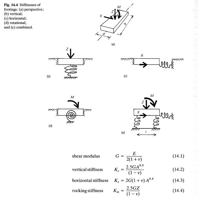
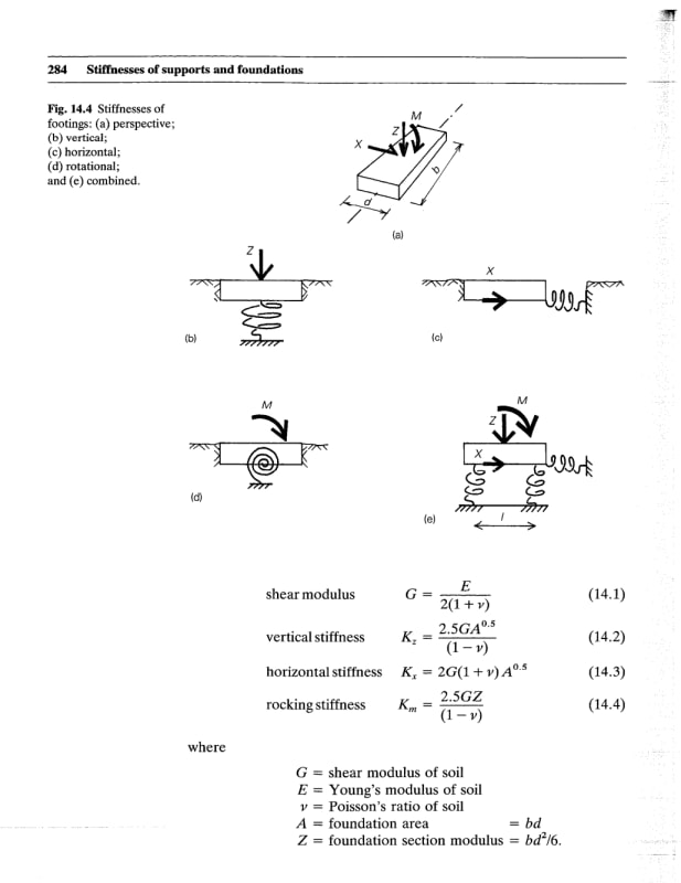
I don't use the program, but it sounds to me like it allows you to model a strip footing (or ground beam) as a line element rather than a plate. In that case, the program needs to know resistance to rotation about the axis of the line element because it doesn't know how wide the strip/beam is. See Figure 14.4(d) below. Does this interpretation make sense?

If so, you can use equation 14.4 from the image, or an alternative is the subgrade modulus * I_footing.

[From Hambly - Bridge Deck Behaviour]
Hambly14_4_a8vxvg.jpg
 
Thanks for the reply steveh49.
Yes, the program does allow the beam to be modeled as line element. I was exactly looking for the reference you have shared. The spring in the pictures represent the soil stiffness right?
If so, how these equations are derived. Does 'E' and 'G' refer to soil's young's modulus and shear modulus?
Why rocking stiffness use 'Z' which seems like vertical load?
 
steveh49 said:
or an alternative is the subgrade modulus * I_footing.
Also, how did you arrive at this?
Can you explain/give reference?
As the units of rotational spring constant are kN/rad in program..
 

Dear MSOUK90,

I am not familiar with SAFE moreover, i look with doubt for the software SAFE ( ALthough a product of CSI , Which is SAP 200 and ETABS also developed by same group)..Iam not sure about type of your analysis .

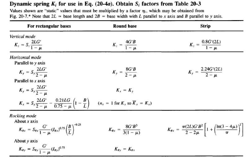
IMO, The term Kθ1 = rotational (dynamic )springs used for dynamic analysis of foundation for vibrating equipment and used for rocking mode . If you are performing static analysis , just provide vertical springs or so ( horizontal springs at some selected nodes etc)..

I will suggest you to look any dynamic analysis and foundations for vibrating eq.

This snap is from FOUNDATION ANALYSIS ( BOWLES)

vibrating_eq.found_rocking_mode_evw43e.jpg
 
My mistake. I clipped out the nomenclature.

Screenshot_20210329-191907_Box_uty2xb.jpg


The equations aren't derived in the book I have. They're simplifications of elastic half-space solutions from these references.

Screenshot_20210329-192026_Box_lmfjpf.jpg


Units should be kNm/rad for what I'm talking about, not kN/rad. EDIT: Realised it's per unit length, so it's kNm/rad/m which gives kN/rad.
 
HTURKAK said:
The term KQ1 = rotational (dynamic )springs used for dynamic analysis of foundation for vibrating equipment and used for rocking mode . If you are performing static analysis , just provide vertical springs or so ( horizontal springs and nodes etc)..
I have never done foundation design for vibrating equipment but I was pretty sure that the 'rotational spring' will be required(and effective) only in such cases.
However, the presence of it in 'line spring' parameters made me curious to inquire about it.
HTURKAK said:
I will suggest you to look any dynamic analysis and foundations for vibrating eq.
Will surely look for it. Planning to purchase Foundation Analysis and Design by Bowles for good(as it seems to be the most suggested book for foundation design- Geotechnical aspects).
 
steveh49 said:
Units should be kNm/rad for what I'm talking about, not kN/rad. EDIT: Realised it's per unit length, so it's kNm/rad/m which gives kN/rad.
Thanks steveh49.
 
If you leave out the rotational spring, you're choosing to model a pin support. This is the case for static load as well as dynamic.

The subgrade modulus * I_footing method is just a rearrangement of M=stress*I/y from linear-elastic materials like steel. Stress = subgrade modulus*deformation. Deformation = theta*y. Rotational spring = M/theta = modulus*y*I/y = modulus*I.
 
steveh49 said:
If you leave out the rotational spring, you're choosing to model a pin support. This is the case for static load as well as dynamic.
I don't think I need rotational spring unless my beam on soil is directly supporting a vibrating equipment. I generally deal with building or industrial warehouse designs.

steveh49 said:
The subgrade modulus * I_footing method is just a rearrangement of M=stress*I/y from linear-elastic materials like steel. Stress = subgrade modulus*deformation. Deformation = theta*y. Rotational spring = M/theta = modulus*y*I/y = modulus*I.
Very well explained. I guess, Deformation = theta*y represents the linear displacement in terms of rotational right? Similar to the arc length?
 
I don't think I've ever used a rotational spring for a beam on elastic foundation. Just vertical springs. (And maybe lateral restraint for stability in FEA software.)

I also notice a lot of dynamic spring constants are being given. That is inappropriate for a static loading problem. Dynamic spring constants are for low-strain displacements and are way stiffer than static spring constants.
 
Maybe it could be used to model a shear key or some other embedded element. Just a guess...
 
Status
Not open for further replies.

Part and Inventory Search

Sponsor