Continue to Site

Eng-Tips is the largest engineering community on the Internet

Intelligent Work Forums for Engineering Professionals

  • Congratulations IDS on being selected by the Eng-Tips community for having the most helpful posts in the forums last week. Way to Go!

ROTOR STACK LAMINATIONS ROTATION-IN ELECTRO MOTOR LOW VOLTAGE 3

Status
Not open for further replies.

rotorgenerator1361

Mechanical
Jun 5, 2016
5
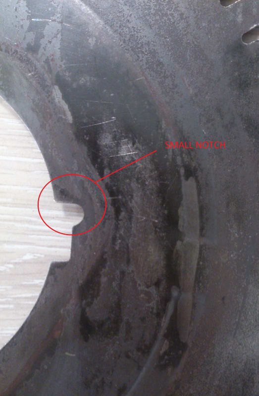
what is a cause of small notch in rotor laminations keyway?
and why it does rotate and move along the rotor stack length?
Does it mean that laminations must be rotated and turnover along with the rotor stack?
 
Replies continue below

Recommended for you

It's difficult to understand/comprehend mechanical arrangements without visual representation.

PHOTOS

Based totally on the vague description of the issue, it's a guess the OP is referring to a poor fit
that exists between the motor shaft and laminations causing it to spin, or rotate.

This guess is like winking at a girl in the dark. "You" know what your doing, but she doesn't.

Post some photos.

John

 
DSC_0025_a9ocdt.jpg
DSC_0026_d2qrp8.jpg


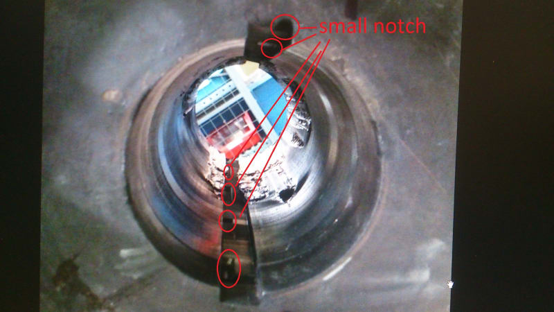
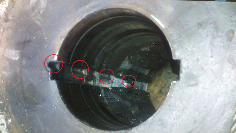
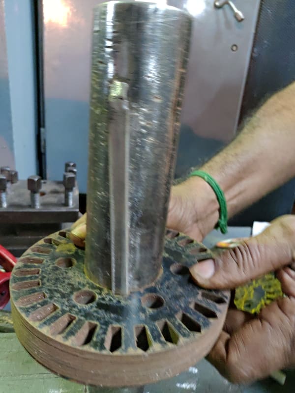
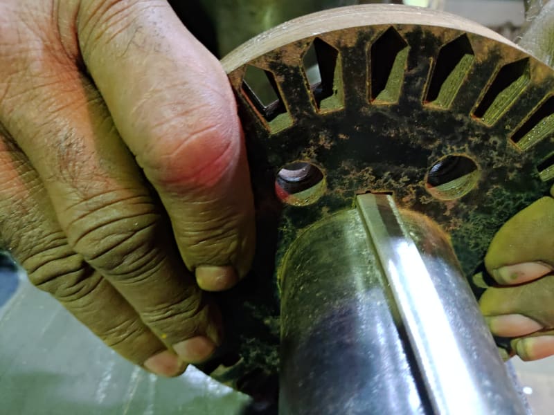
Please consider the attached photos, I hope the enclosed picture help to clarification about the notch in the rotor laminations.in addition, this notch moves and changes position along the stack in key ways.
 
That is the assembling notch which shows the punching direction. When the core punched out, there will be burrs at the edges. When you stack the core, you align the core for the semi circular notch so that all the burrs are in the same direction. If you do not align the notch, like flip the plates, then the burrs will bite into each other creating stacking issues and possible core shorts. Sometimes, there is also a guide pin in the notch used to assemble the core and it is pulled out once the assembly is done.

Muthu
 
Thanks Edison. That's my something new for today. lps

Bill
--------------------
"Why not the best?"
Jimmy Carter
 
me too. I knew they had to keep track of the orientation, but I never knew how they did it.

=====================================
(2B)+(2B)' ?
 
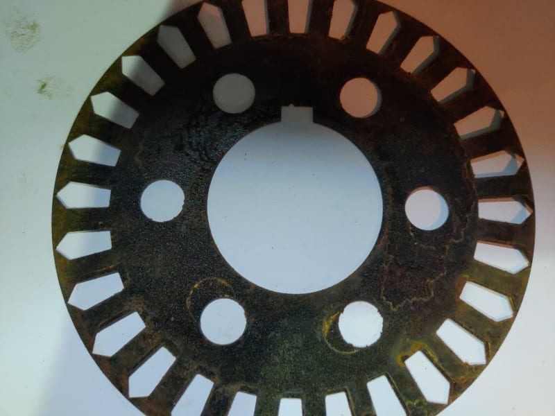
Could that also be a flow channel to help varnish impregnate the laminations? The round notch widens one of the square notches.I see tolerance match-up problems to get laminations to fit tightly to the shaft and two keys. Are the round notches all one side or alternating sides for balance when stacked?
 
Thx guys.

CP - The plates are usually pre-varnished during manufacture as sheets before punching. If the laminations are laser cut (which is fashionable now), then they are post varnished after cutting since the edges get burned during laser cutting. No varnishing is done after stacking. The notch is one side only so that you can't flip the plates horizontally or vertically during stacking. I agree that two key ways do not make sense and will create match up issues. Probably, they use only one key way in this case. OP can clarify.

Muthu
 
in this type of motor, there is a skewed angle during stack and small notch move irregular in the corner of keyways, Could this be due to the rotation of the sheets or turn over the sheets during stack?
and Is it necessary to have a rotating or turn over the plates in the rotor stack?
 
Does the key way in the shaft match the rotor slot skew which is usually one slot pitch? The notch should line up for every plate. Post the rotor shaft pic with the key way.

Muthu
 
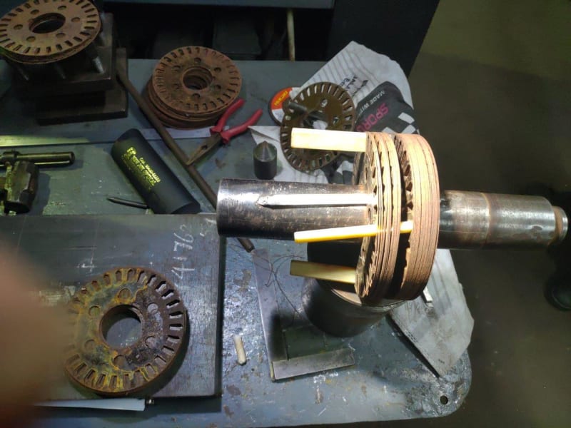
no, it doesn't match the keyway in the stack and skew. actually, there isn't keyway in the shaft.
DSC_0057_ekyneo.jpg
DSC_0058_wz8aae.jpg
 
Good demo! It's obvious from that the stacking skew controls the slot skew.

=====================================
(2B)+(2B)' ?
 
There is something in power transformers about grain oriented steel, Wikipedia suggests it could only make iffy tradeoffs in regards to motors (not my area of design). If nonetheless the motor maker wants to take a roll of oriented steel, feed it through a punch and stack in on the rotor then what ever asymmetry is in the sheet is going to be asymmetry in the rotor. We are just running a thread on 2x motor vibration. Could the motor maker have wanted one of the advantages of oriented steel and so alternated stacks of say 20 or 40 laminations in his rotor to preserve symmetry in it and thus keep the vibration down? Okay, a Long shot but we're getting stuck here.

Bill
 
1361, does the stator have distinctive keying or stacking?

Bill
 
stator only has some track of cleating machine in outer diameter and there isn't any skewed angle or key, On the other hand, the rotor has two straight keyway and small notch with the skewed angle in slots, but I don't know rotor laminate had rotation or turn over before punching for orientated effect, and it's necessary for rotor or not?
 
Some motors skew the rotor lams, some skew the stator lams, and some don't skew either. It is a motor design issue.

= = = = = = = = = = = = = = = = = = = =
P.E. Metallurgy
 
Edison123, and all,
Thank you for that demonstration!

Do you have any books/manuals/texts that you can recommend which describe motor design at this level of detail?

I have a few electric motor design books, but they are pretty theoretical. For example, Richardson's textbook. They describe the types and how to hook them up.
None of them ever mention a useful detail such as the laminate stacking order and how they are skewed. Or other details, for that matter, such as the thickness of laminations, depth and shape of the slot, type of material, etc.
When I look at a publisher like Pearson, or this big name: CRC Press I can't find anything with much detail.

 
I haven't seen a lot of textooks that go into a lot of details of motor construction and repair rather than theory.

For $15 USD, you can pick up an antique copy of Rosenberg's Electric Motor Repair, which is sometimes referred to as the motor repair bible by oldtimers.

EASA has some pretty good stuff, although some of it's a little pricey.

=====================================
(2B)+(2B)' ?
 
Already got Rosenberg's Bible (but thanks anyway Electricpete!)

The other stuff is more than a little pricey...

A bit of background about why I'm asking...

The method I used still was pretty crude. Flat magnets and round inner stator = big air gaps.
Rectangular magnets and discrete pole regions = distinct cogging forces.
Somewhat mitigated by the alternating pattern of 1" and 1/2" magnets.
Looking for ideas and methods to do this better next time.

 
Status
Not open for further replies.

Part and Inventory Search

Sponsor