Continue to Site

Eng-Tips is the largest engineering community on the Internet

Intelligent Work Forums for Engineering Professionals

  • Congratulations KootK on being selected by the Eng-Tips community for having the most helpful posts in the forums last week. Way to Go!

Round HSS moment connection 1

Status
Not open for further replies.

Nitesh Sadashiva

Civil/Environmental
Jan 9, 2020
33
Hello all,

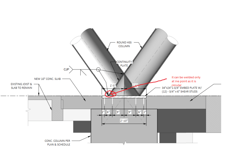
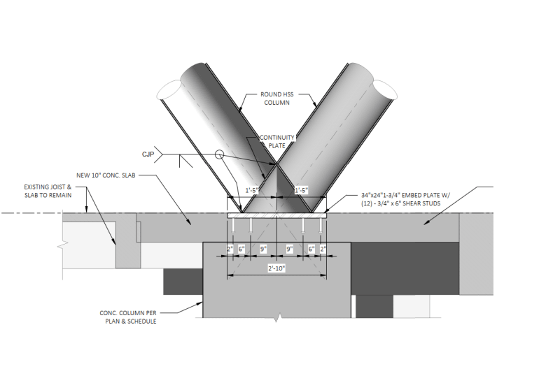
I have a condition where two round HSS columns (HSS20x0.500) are connecting to embed plate as shown in the sketch. EOR has specified the design moment of 100K-ft along with 100 Kips compression and 20 Kips tension (ASD values). The sample detail provided by EOR shows continuity plate. Since it is a round HSS, I am not sure how this continuity plate can be provided for round HSS. Anyone came across the similar connection? Any design example for similar case is much appreciated.
HSS_connection_prylgy.png
 
Replies continue below

Recommended for you

For Similar types of connections I would check design guide 24, chapter 8, and 9 you will find useful examples and tables there.

AS for the continuity plate, I think it can be added, the EOR already specified a CJP with a groove from one side which can be easily done as the plate is not that far away inside the branch member.


ôIf you don't build your dream someone will hire you to help build theirs.ö

Tony A. Gaskins Jr.
 
Malikasal, thanks for your response. However chapter 8 in AISC design guide is for axial only members. But there is a unfactored moment of 100 k-ft at this joint. Chapter 9 is for moment connections. But unfortunately, it checks only chord plastification. In this case there is no chord. It is connecting to embed.
Also, if we provide a continuity plate, it has to be round plate. So the bottom of the continuity plate marked in the sketch will be welded at a single point. I am not sure how we will prove that it is adequate.
HSS_connection_hcvzsr.png
 
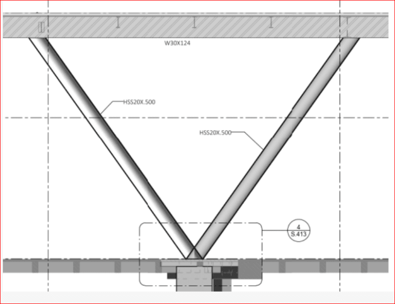
I’d be interested in seeing the bigger picture. How are you getting moment at this joint?
 
Ah don't you just love engineers who expect other people to design and fabricate near impossible connections!

If I was being cheeky I'd ask for a the engineer to provide a full picture of his connection in 3D. If I was going to be more polite I'd ask if a thick slotted plate in the plane of the moment could be used. Though if this is architectural then you might struggle with such a request.
 
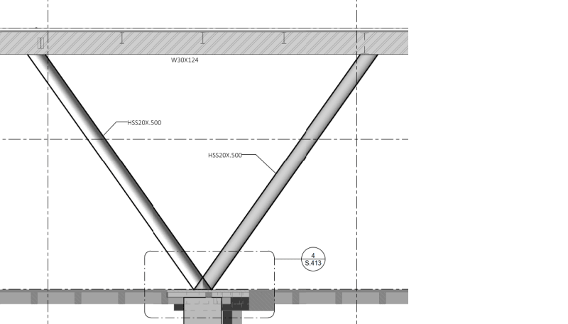
@MIStructE_IRE Please see below picture. When we requested the loads in an RFI, EOR provided the moment at the joint.
Untitled_wsjzsp.png
 
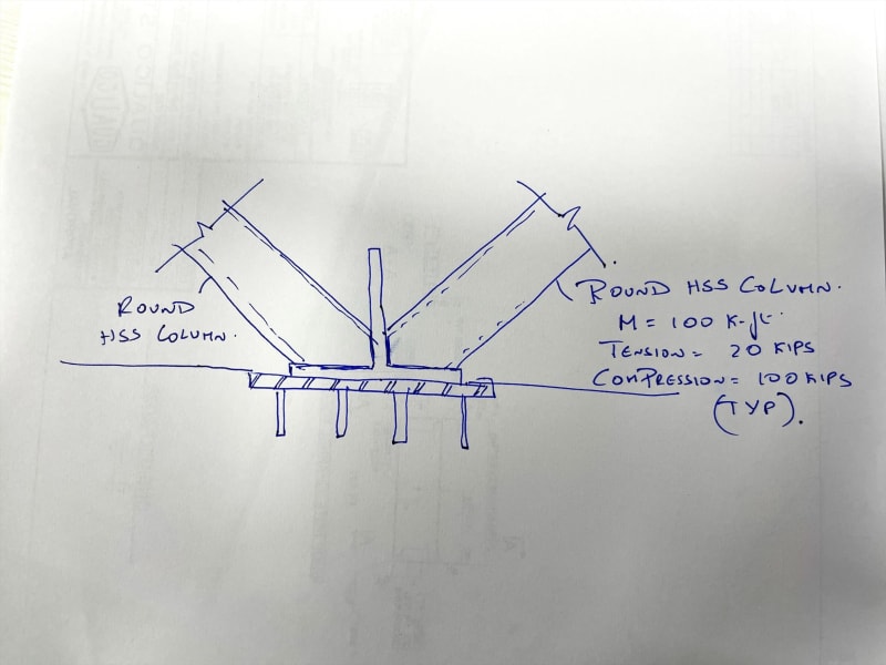
Use a vertical plate, making an inverted tee with the embed plate. Extend both HSS sections to meet the tee shape.

BA
 
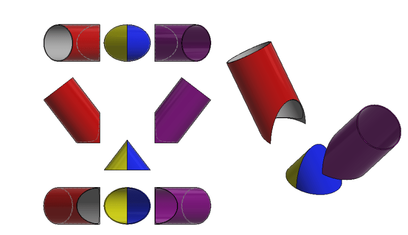
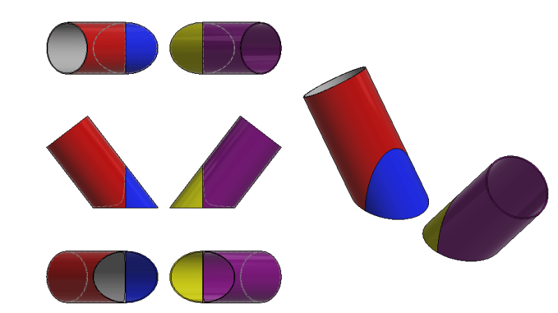
If it must be done this is how you would do it. It can be done with 2 sections of pipe HSS cut and the same angles and then rewelded to create a "cone". The weld the two lengths of pipe to this cone. See drawing below:

Third angle projection, sections offset for clarity.

pipe_mrdlek.png


If possible I'd choose to use a section of pipe with greater wall thickness to manufacture this connection.
 
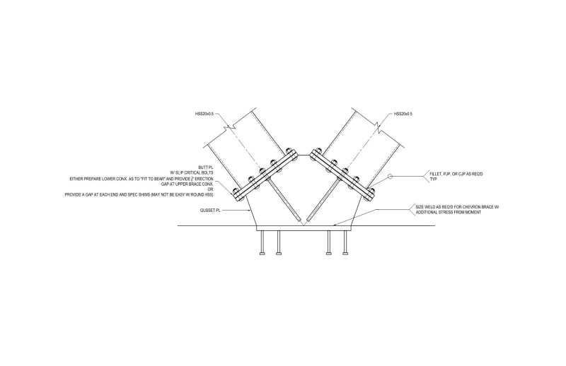
@BAretired Are you suggesting something like shown below? if so, what are the applicable limit states you think of for this connection?
IMG_0352_ya2dwi.jpg
 
@human909 This looks great. But I am not sure whether the fabricator will be able to do this.
 
Nitesh sadashiva said:
@human909 This looks great. But I am not sure whether the fabricator will be able to do this.
No problems.

It is actually 'easier' to fabricate than it looks. You don't need any extra plate as the plate sections are made from cut off HSS. Cut the HSS, bevel edges then buttweld (groove weld). Then attach the cut pipe and weld again. To make it easier to see visually this is the same parts as before rearranged:

pipe2_z2zhfk.png


But like I suggested first post, This connection as detailed should be substituted for something else. BAretired's you drawing about without as much T projection might be easier.

EDIT or rearranged again:
pipe3_rjkt68.png
 
Nitesh sadashiva said:
Are you suggesting something like shown below? if so, what are the applicable limit states you think of for this connection?

@Nitesh, I belive BA is saying turn the plate 90 degree to what you have sketched, then you'll create a knife plate conneciton condition for each round HSS tube and it becomes a simpler connection, but not as pretty
 
@spieng89 If we create a knife plate connection condition, how we will justify the moment transfer between the round HSS and knife plate?
 
I would likely ask the EOR if they would be OK with this concept. It's easier to erect and fabricate.

Id_try_this_vwussn.jpg


Edited to add .pdf because my sketch is fuzzy.
 
@DrZoidberWoop I liked this concept. But do you have any reference to check circular bolted end plate for the moment? If it was just axial force, I had no issues in providing the connection as you have proposed. Since the moment is involved, I am not sure about how I will ensure HSS to round end plate bolted connection is adequate against moment..
 

Can you use a solid milled piece at the joint?

If I were reviewing it I’d be equally concerned about how the embedded plate with the studs sucks up the 100’-k plus tension force.
 
There are a few threads on this website asking about moment connections w/ round hss/pipe.

I believe the consensus was that CIDECT DG1 and AISC DG1, 24, & 29 have sufficient information to design the connection and evaluate member integrity.

Steel Tube Institute has a concise breakdown of some HSS wall limit states, including moment on round HSS. There is also a lot of more detailed literature out there.


However, this might be a waste of time if your EOR/architect prioritizes the HSS looking pretty over the connection being practical.
 
Nitesh said:
@BAretired Are you suggesting something like shown below? if so, what are the applicable limit states you think of for this connection?

Exactly, but I don't understand the meaning of the second part of your question. Theoretically, the full strength of the HSS members can be developed but the welding is done in the field, so some conservatism may be warranted.

I don't know how a moment of 100'k can be developed in these members, but if that is what the EOR requires, I think I prefer the detail proposed by DrZoidberWoop.

BA
 
I just looked a little more carefully at the sketch, which is repeated below. Is it really an HSS20x0.5? That is huge. The axial loads and moment stipulated by the EOR are trivial for that section. Forget about the vertical plate. Butt weld the HSS members together and use a fillet weld to the embed plate.

Capture_hrsc92.png


BA
 
Status
Not open for further replies.

Part and Inventory Search

Sponsor