Eng-Tips is the largest engineering community on the Internet

Intelligent Work Forums for Engineering Professionals

Rupture disk downstream of a PSV piping system

Status
Not open for further replies.

SNagri

Chemical
Aug 12, 2024
4
0
0
US
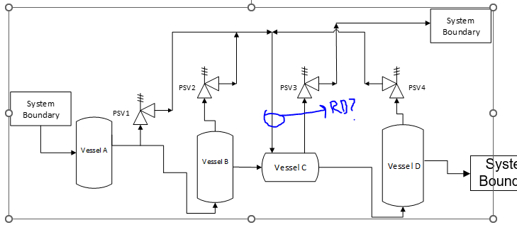
I am investigating a reliability issue with some PSVs in our system and would like to explore potential solutions. As depicted in the attached diagram, PSVs 1, 2, and 4, located on vessels A, B, and D respectively, discharge into Vessel C. Subsequently, PSV 3 relieves the pressure out of the system boundary.

This setup was implemented by an engineering company long ago, based on a study we currently cannot locate. The issue we face is corrosive material buildup at the outlet of the header where PSVs 1, 2, and 4 discharge into Vessel C. This buildup leads to corrosion of the bellows and other parts of PSVs 1, 2, and 4, causing reliability problems.

I am considering the installation of a rupture disk at the point where the common header, discharging PSVs 1, 2, and 4 into Vessel C, connects to Vessel C. The rupture disk might protect these three PSVs. However, there are challenges: PSVs 1 and 2 share a similar setpoint, whereas PSV 4 has a different setpoint, and the operating pressure in Vessel C differs from the other vessels.

Is it feasible to install a single rupture disk downstream of these three PSVs to protect them individually? Additionally, what would be the appropriate set pressure for the rupture disk in this scenario?[URL unfurl="true"]https://res.cloudinary.com/engineering-com/raw/upload/v1723474635/tips/PSV_system_upet27.emf[/url]
PSV_System_xf9ur3.png
 
Replies continue below

Recommended for you

Can you put numbers to these set points?

It's definitely rather odd.

I think No is the answer. A RD requires know pressures either side - at present it looks to me like you could get equal pressure both sides or a variable pressure.

Also relief valves have a tendency to simmer and hence your RD could rupture with very little flow. Then you need to shut down while you empty everything and replace it.

I've seen RDs upstream of PSVs before where they didn't want fugitive emissions or leakage until it was really required, but nothing quite like this.

If you don't know why it was done this way, I would start form scratch and develop a proper relief philosophy and design that you can hang your hat on.

Why not just pipe them all to the "system boundary" either in one header or individually?
Why are you getting flow of vapour back to the bellows?

Remember - More details = better answers
Also: If you get a response it's polite to respond to it.
 
SNagri ...

"This setup was implemented by an engineering company long ago, based on a study we currently cannot locate"


Bwhahahahahaha !!!

I am confused ... can you explain why you said this ? ... Some companies require PE Stamps on ALL PIDS !

If Company A develops Block Flow/PIDs for Company B ... BOTH COMPANIES SHOULD BE NOTED ON SCHEMATICS !

I agree with LI ...

Also, how are PSV2 and PSV4 suuposed to actuate when the pressures on the inlet and outlet are (virtually) the same for each ?

Or maybe I don't understand ...

MJCronin
Sr. Process Engineer
 
PSV 1 and PSV 2 have a set pressure of 95 PSIG, while PSV 3 and PSV 4 are set at 60 PSIG. As mentioned earlier, these PSV outlets were rerouted due to a dispersion modeling study sometime in the 90s, which recommended venting these three vessels into a common header and a secondary vessel.

Ideally, we should rework the entire piping for the PSV outlets of PSV 1, PSV 2, and PSV 4, as they have experienced repeated corrosion-related failures. PSV 3, however, is performing well because it does not experience significant back pressure.

I am considering ideas to maintain the current system while protecting the PSVs without having to change the piping network completely.
 
I apologize for any confusion; I didn't mean an engineering company implemented it the change. I've simplified the P&ID by removing some specifics. The engineering company recommended certain routing, but since this was done a long time ago, we only have some references to it. Thats besides the point why they did that. I am just asking for opinion on whether a rupture disk can applied in such a situation downstream of the PSVs?
 
Do you have a formal HAZOP for this system that would explain PSV actuation and the operating/load cases ?

MJCronin
Sr. Process Engineer
 
Why would you discharge three relief valves into a vessel with another relief valve. There seems to be something against Codes here or at least very poor engineering practice.

Why would you put a rupture disk to block flow on the downstream of the three relief valves. It is usually put upstream to prevent corrosive fluids to be in continuous contact with PSV. Every time one PSV goes off it will rupture the disk so what purpose does it serve?
 
ruptureDisk_alsfez.png


It seems clear to everyone that the current design, implemented many decades ago, is bad. We're exploring potential solutions, such as rerouting the outlets of these three problematic PSVs outside the system boundary directly. This would require collaboration with an engineering company that specializes in relief header routing.

However, I'm also curious about other possible solutions. Regarding code compliance, the three PSVs in question are balanced bellows types. The operating pressure of the vessel they relieve into(vessel C) is 30 PSIG. For PSV1 and PSV2, the setpoint is 95 PSIG, so the back pressure is not more than 50% of the set pressure.

I recently came across a document that mentions the possibility of installing rupture disks downstream of a PSV in certain situations. I'm sharing this because the rupture disk could prevent corrosive materials in the relieving header from backing up against PSV1, PSV2, and PSV4, thereby protecting the bellows from damage.

While PSV3 seems to be functioning properly, the issue primarily affects the PSVs that are backing up against vessel C. Our working theory, confirmed by metallurgical analysis, is that the material in the pipe is causing corrosion in these PSVs. In theory, a rupture disk downstream of the PSV could protect the internals of PSV1, PSV2, and PSV4 from damage.

I’d like to brainstorm with others who have more expertise in this area to explore these ideas further.
 
PSV discharge must always slope down in to the common discharge gathering header, ie the PSV must be at high point. This prevents corrosion debris and condensed liquids from travelling back and accumulating at PSV exit port. And entry into gathering header must be at top of pipe.
My guess is you've currently got all these PSV's discharges rising UP into the common gathering header which leads into vessel C.

Otherwise, an alternative solution may be to add a low point drip leg on each of the discharge piping of PSV 1, 2 and 4 and route these lines (slope these drain lines continuously downward, preferably 2inch corrosion resistant material piping) into vessel C.

Rupture disc downstream of PSV will most likely not help - PSVs' all leak a little in real life, so RD will blow and you'll be back where you started.
 
So are you saying that the fluid in the downstream vent piping is more corrosive than the fluid upstream of the relief valves as the header takes other PSV discharge from more corrosive fluids than the systems that these PSV's relieve from. If so then I can see why you would have a rupture disc on the outlet similar to why you have one on the inlet if the inlet was a corrosive fluid. However, is putting one common rupture disc better than installing one on each discharge? I think it would be better with one on each discharge since it is 3 times more likely that 3 PSV would blow at any given time than one so you would be changing a common rupture disc 3x as often.

As far as limiting the back pressure I don't think so. Once the PSV pops it will see the same superimposed and same built up backpressure, even more since the rupture disc will produce more built up back pressure.

As for checking whether relief valve is leaking - maybe but a leaking valve could also be due to simmering where the upstream pressure gets close to relief pressure but the seats may still be OK. The pressure is likely to build up to a point where rupture disc ruptures before the PSV is properly inspected to know the cause of leaking.

Why do you have a PSV in series with all the three process PSVs? If you would remove that PSV then in effect all of the other PSV's would then discharge directly to the vent system and the vessel that the PSV was removed can just serve as a knock out drum.

When you state that the backpressure is not more than 50% of set pressure what you are referring to is the superimposed back pressure which is a constant downstream header pressure that exists regardless of flow. I assume this constant downstream superimposed back pressure is due to the set point of the PSV 3 being 30 psig so a pressure of 30 PSIG maximum is maintained upstream of PSV 3. However, the actual pressure upstream of PSV 3 is really the set pressure plus the allowed overpressure to get full flow out of the valve plus the actual frictional pressure loss from PSV 1, 2 or 4 to the inlet of PSV 3 when relieving. This should be checked to make sure the resulting pressure is within the balanced bellows backpressure limits for the given manufacturer.
 
@SNagri
Additionally, what would be the appropriate set pressure for the rupture disk in this scenario?
PID is incorrect as pressure in subheader between PSV and RD is uncontrolled. RD set pressure depends on how you are going to control it.

Note that set pressure is unaffected by backpressure as set pressure is referred to the PSV upstream pressure. What you are asking is the bench test pressure or the seat dif pressure.

It seems clear to everyone that the current design, implemented many decades ago, is bad.
For me it is not clear the design is bad. What is wrong with this design (except minor issue with downstream pressure control)? Why it is 'bad' whatever this means? The design is not able to be 'bad' for itself, is it? There should be some reason behind that.
You should find out whether these PSVs are classified as multiple devices or not to ensure that activation of any of PSVs does not disrupt other PSVs.
2.4.4 Devices in Combination (Series)
Relief device combinations are normally used to take advantage of or combine specific characteristics that are not found in individual devices. The following are the most commonly used combinations.
Rupture disk upstream of a pressure relief valve: This is by far the most common combination used in the process industries. The benefits include:
* Prevention of leakage through the relief valve
* Prevention of product buildup in the valve nozzle
* Isolation of valve components from corrosive processes
* In-place pop testing of the relief valve (the value of this practice is not universally accepted in industry and only a few rupture disk types are suitable for this activity)
Rupture disk downstream of a pressure relief valve: This is typically accomplished with a low pressure rupture disk. The primary benefit is to prevent corrosive vapors in common headers from entering the discharge side of the relief valve.
Rupture disks in series: These can be factory supplied double disk devices or individual devices installed in series. These are typically specified for one of two applications.
* Highly corrosive or otherwise aggressive environments that are prone to disk failure with the goal of having the second disk remain intact to provide time for a safe shutdown without a discharge event
* To isolate the process side disk from variable back pressure in a common header
Virtually all of these combinations have a common disadvantage in that most of these devices are affected by the pressure differential across them and therefore the space between them has to be monitored and/or vented appropriately to ensure safe operation. Additional guidance regarding the use of combination devices is found in Section 2.5.5.2.
...
2.5.5.2 Installation Practices
Published installation practices for various configurations of devices in combination are given in the following paragraphs.
Rupture disk upstream of pressure relief valve (combination devices): These are treated explicitly in the ASME BPV Code wording above. The devices may be installed close-coupled or some distance apart. The disk device must be a nonfragmenting style and the space between the devices must be provided with a suitable telltale indicator as described in 2.5.5.3 below. The set pressure of the valve should be at or below the disk burst pressure (so that flow is not interrupted even momentarily during the disk opening period).
Rupture disk downstream of pressure relief valve: The rupture disk can be installed immediately downstream of the valve or some distance away. The space between the valve and disk must be vented or monitored to prevent pressure buildup at the outlet of the valve. A small vent hole is often utilized.
...
4.6 MULTIPLE DEVICES
4.6.1 Multiple Devices in Parallel
Relief devices are installed in parallel for any or all of the following purposes:
* to provide installed spares (normally valved off)
* to provide sufficient relief area (more than one device on line)
* to provide staged relief (on-line devices with staged areas and set pressures)
Devices in parallel are sized individually for the respective specified services. Parallel devices differ from devices in series in that no combination capacity factor is defined or needed. If devices in parallel share a common vessel opening, the internal cross-sectional area of this connection must be at least equal to the combined inlet areas of the devices. Avoid the use of rupture disk devices in parallel on a common vessel opening. The inlet loss to any device must meet the required criteria for that device when all online devices on a common opening are open and flowing.
When using pressure relief valves in parallel to meet the required relieving capacity, consideration should be given to the size and set pressure of each valve and the various overpressure scenarios to minimize the likelihood of unstable valve operation. A factor of four in relieving loads between the two valves has been suggested as a good general practice. The valve manufacturer should be consulted for guidance for specific valve models and conditions.
4.6.2 Multiple Devices - Rupture Disk Device Upstream of a PRV
...
4.6.3 Multiple Devices - Rupture Disk Device Downstream of a PRV
In this case a combination capacity factor is not used, but the flow resistance of the rupture disk device must be considered in the calculation of built-up back pressure on the pressure relief valve.
Source
Can you describe what is the cause of 'repeated corrosion-related failures'?


RD is usually used to avoid corrosion on SV, you could install it at each SV.

What is not good engineer design is discharging the sv to a vessel, and from it setting a sv to the flare system.

This design is used with a recycle pump, for hazardous relief products to recover liquids to the process or storage tank, if this is your case, you should have a process design experience team, hazop, and dynamics simulation, to check if your design is reliable.

We installed into a PVC process, a similar system because the reactor volume of each reactor (2 reactors online) was fixed to discharge at emergency conditions, and the entire relief system has a maximum volume of liquid and gas to handle.

Horacio


Horacio

linkedin.com/in/horacio-torres-molina-429a7b1b
 
Status
Not open for further replies.
Back
Top