Continue to Site

Eng-Tips is the largest engineering community on the Internet

Intelligent Work Forums for Engineering Professionals

  • Congratulations KootK on being selected by the Eng-Tips community for having the most helpful posts in the forums last week. Way to Go!

Safe Working Load for Steel Cables in Public Art

Status
Not open for further replies.

Deefer

Structural
Mar 2, 2021
7
Hi Everyone. Safety and structural engineering question for you experts.

I'm designing a structural frame for an outdoor public art display. Two vertical steel cables will be tensioned from a horizontal metal rail down to concrete flooring 8 feet below. The two cables have about an 8" gap between them. Aluminum discs will be attached to the cables via four holes drilled into each disc. Here's a visualization of the frame, showing a series of the two-cable setup I've described.
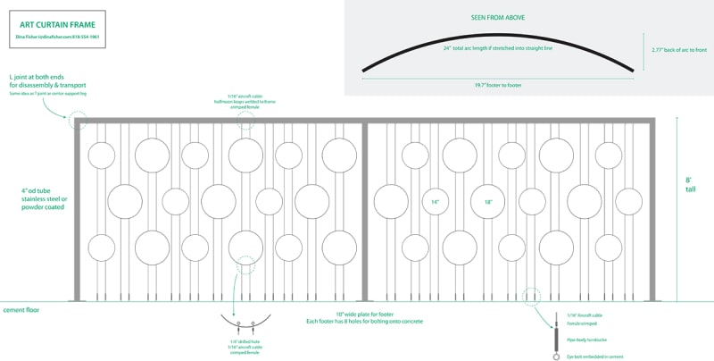
curtain_frame_v02b_fc81k8.jpg


I need some advice on making sure my cables and cable rigging are strong enough to withstand public interaction. This could take the form of a grown 240 pound man falling against or trying to jump onto the suspended aluminum discs. I was originally thinking a 500 pound working load for EACH cable would be sufficient, but am thinking that may not be enough. Whatever working load I settle on, I'll of course make sure my weakest link in the rigging can bear that load.

What are your expert thoughts on a safe working load to design for? I'll be monitoring this discussion to answer questions in case I left out significant details.

The frame uses 4" OD 11 gauge stainless steel tubing (but correct me if I'm wrong), so I'm pretty sure the frame will be strong enough. The cables need to be tensioned just enough so that the lines remain fairly taut when people try to mess with them. The aluminum discs are 14" and 18" wide x 1/8" thick.

Thanks in advance for helping improve public art. Folks in the materials engineering section were super helpful with aluminum/stainless corrosion.
 
Replies continue below

Recommended for you

The green text on your sketch is too small to read (for me). Not sure how important it is, though.

I don't think there is a need to worry about a heavy man falling against the discs because tension in the cable increases as lateral force is applied. If he climbs or jumps onto the discs, tension in the upper part of the cable increases by his weight times an impact factor of, say 2 or 3. To me, that seems like an unlikely scenario, but who knows about art lovers?

Stressing a cable to a particular tension and maintaining that stress is a problem, even when the cables have been prestressed beforehand. Cables tend to stretch with time and lose tension. I suspect you are going to be re-tightening the cables as they loosen. And as you tighten one, others loosen due to beam deflection.

I think your major problem is going to be designing the curved top beam to withstand the tension of all of those cables. I seriously doubt that 4" OD 11 ga. steel tubing will do the job, but that is largely dependent on the magnitude of the cable tension which has not yet been determined.

BA
 
The horizontal stiffness will always have some value, which will increase by increasing the pretension axial force. The point is to determine the tolerated stiffness (applied horizontal foce/developed displacement) in order to choose the pretension force according to catenary thoery. I woulg suggest a maximum displacement of 1/2" when a 240 pound man falls against it. These data may be sufficient to calculate the required force. Moreover, you can specify top/bottom regulators so that pretension can aftwerwards change if the weight of the suspended objects changes.
 
Well in the mining industry when we have perhaps 50 or60 men hanging off the end of a 6000 or 7000 foot steel cable ( man cage on the end of a hoist rope) we use a FOS of 10:1 and we retire the cable every 24 months. Take that for whatever you think its worth
 
Thanks for your replies! Questions:

1) BAretired is concerned the 4" OD x 11 gauge stainless steel beam will not be sufficient. If I bumped that up to 13 gauges would that suffice? If not, what is suggested?

2) I had not considered pre-tensioning the cables. I'd appreciate pointers on the process, amount of time, whether they would "contract" affecting installation procedure (I'll read up on it, but appreciate this forum's expertise!).

3) I'd planned on using closed-body turnbuckles with 3" of expansion. Now I'm wondering whether I'll need more than 3" of adjustment leeway due to cable stretching. What would you recommend?

p.s. The green text is not important in the image posted.
 
Deefer said:
I had not considered pre-tensioning the cables.

I would consider pre-tension. A simple non-linear (large disps) static analysis in sap2000 may easily yield the desired data.
 
Falling against it is one consideration for overall lateral stability of your frame. As such you’ll want fixed bases.

I wish I could say I’m mature enough not to climb that after a night on the town... Your top horizontal member would therefore be required to support the weight of me, and my college buddies, as we race to the top! As its curved, you have combined bending and torsion to consider, and the 4” tube sounds way too small to me for that.

Having climbed this every saturday night for 6 months your cables will begin to slacken, so you’ll want adjustable turnbuckles and a client willing to adjust them every year or two.

Disclaimer... I may or may not do this after a load of pints.. but someone will!
 
Consensus seems to be my 4" tube is not beefy enough. What size and gauge stainless do you folks recommend?

I totally agree people will climb on this thing, half my friends would. :)
 
deefer,

You have eleven columns of aluminum discs in each frame section. The top beam is curved in plan view with a chord length of 19.7' and a maximum offset of 2.77' at midpoint, if I am reading your text correctly.

Each column of discs has a pair of cables, each tensioned to some value yet to be determined, but the figure of 500# has been mentioned as a starting point. There are 22 cables in all with a total estimated tensile load of 11,000# for each half of the frame.

If the top beam is spanning 20' as a simple span, with no curve, the moment is 11,000*20/8 = 27,500'#. Using a 4" OD x 3/16" Hollow Circular Section, S = 2.05 in[sup]3[/sup]. The stress would be 161,000 psi, well beyond the strength of any available steel.

13 ga. is not bumping it up. It's bumping it down. The larger gauge indicates a smaller thickness. According to the United States Standard Gauge, 11 ga. is 0.1196" thick whereas 13 ga. is 0.0897" thick, both less than 3/16" (or 0.1875").

Adding a curve to the top beam makes matters considerably worse because the effective span is longer and there are significant torsional stresses to be considered.

My best advice to you is to find a structural engineer who can work with you on your project. Hopefully, together, you will be able to come up with something suitable.

BA
 
Deefer - looks like an interesting art installation. I'd recommend you hire a local structural engineer to work with you in the design if public safety is a consideration in the design (which I agree it should be). We can give some rough ideas, but unless a full analysis is done I doubt anyone would be willing to give a definitive answer.
 
We sometimes take on some pro bono work for a local artist to assist with competition entries. If she’s successful we’ll get a nominal fee, if not no big deal, I got to scheme design something interesting.

You might find a local structural engineer as generous as my good self!
 
Thinking about it a bit more, I see no reason to be concerned about the lateral deflection when a big guy falls against the discs. Who cares? Tighten the cables just enough so they are reasonably straight with nobody climbing on them or falling against them. Anyone who climbs on the discs will be adding his weight to the top beam, but there will not be a large stress from the rest of the cables.

BA
 
Thanks everyone for your input. I'm realizing this is far more complex than I'd imagined. Will try finding an engineer who can work within a public art budget.

But first, I think BAretired misunderstood the 500# starting point. I mentioned 500# max working load for cable rigging design, so each cable could withstand a big guy jumping on a disc. So I'm guessing the 500# x 22 ==> 11000# for each side is far more stress than would actually occur from cables tensioned just enough to stay straight. Any last thoughts on this would be appreciated, so I can better understand the situation moving forward.
 
Deefer,

I was under the impression that you were going to prestress the cables to 500# each. If not, a working strength of 500# per cable seems reasonable. With a safety factor of 5, that means a breaking strength of 2500# per cable.

BA
 
why not talk to some barrier cable vendors or architectural cables used for stairs and similar. like this
or
I know yours is vertical but it is essentially the same stuff.

they might really like getting involved with some art and have seen it all before.

Personally I wouldn't overthink this or you'll end up with cables that would hold up a suspension bridge.

If it works for cables to stop people falling through barriers, it will work for your art work.


Remember - More details = better answers
Also: If you get a response it's polite to respond to it.
 
Status
Not open for further replies.

Part and Inventory Search

Sponsor