Continue to Site

Eng-Tips is the largest engineering community on the Internet

Intelligent Work Forums for Engineering Professionals

  • Congratulations KootK on being selected by the Eng-Tips community for having the most helpful posts in the forums last week. Way to Go!

Sap Shell Modeling

Status
Not open for further replies.

MCR Kumara

Structural
Jul 14, 2019
4
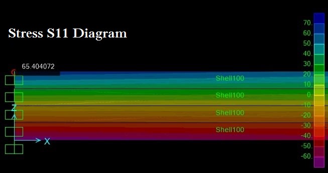
Shell modeled in X-Z plane and load also applied in along Z axis as cantilever beam. m11 stresses different from calculated stress why?
 
Replies continue below

Recommended for you

How about providing your model, an example calculation, a picture, a sketch, really anything to show the issue, your description is quite vague as to what you are exactly modelling, how you are calculating stress to compare, etc, etc.

I don't mean to be rude but do you think you could determine the cause of what you are seeing from the explanation you gave?


shell thickness is 100mm and width is 300mm. As cantilever beam i can find stresses using My/E.
2C_m5mmkp.jpg

Load is verical z direction
 
Further out in the span is the stress more in line with a hand calc?

I suspect due to the discrete supports and lack of meshing, that load is concentrating or tracking towards these points, so it won't agree with a hand check right where your cursor is located. Further out in the span I'd expect with some fine meshing that it would be closer to your hand check where the stress is more uniformly distributed.

You don't say what hand calculated stress you are expecting to compare to the 65 (MPa presumably) to?
 
Maximum Stress = MxY/I = 50x10^6x100/(1/12x100x200^3) = 75(N/mm2)
 
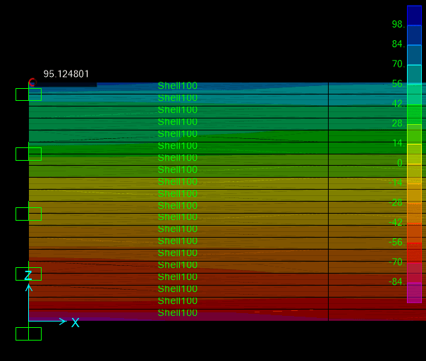
i incresed the mesh then stress is over to calculated one
112_prqzav.png
 
Try dividing it so it's a 1:1 aspect ratio. Keep dividing it until it starts to agree with your hand calculation somewhere out in the span remote from the support. Stop checking it at the support for the reasons I noted in my second reply, it won't be correct.
 
Your finite element model is quite wrong, so it is only normal for you to not get the expected results.

1st, the aspect ratio of the finite elements should be close to 1:1, as mentioned by the previous poster.
2nd, you should input restraints to all nodes on the boundary condition side of the shells.

I believe you need to study a lot more about finite elements and FEA before you venture yourself in these tools.

Best regards,
Filipe

 
Status
Not open for further replies.

Part and Inventory Search

Sponsor