Continue to Site

Eng-Tips is the largest engineering community on the Internet

Intelligent Work Forums for Engineering Professionals

  • Congratulations waross on being selected by the Eng-Tips community for having the most helpful posts in the forums last week. Way to Go!

SAP2000 Cables large displacement and warning modelling

Status
Not open for further replies.

Teiko

Structural
Dec 27, 2022
5
Hi guys,I have troubles moddeling a vertical support with cables. when I chargue the structure with seismic loads Ex (horizontal), Ez (vertical)

image001_ddfusl.png

image002_pabbgx.png

image003_fxncpw.png


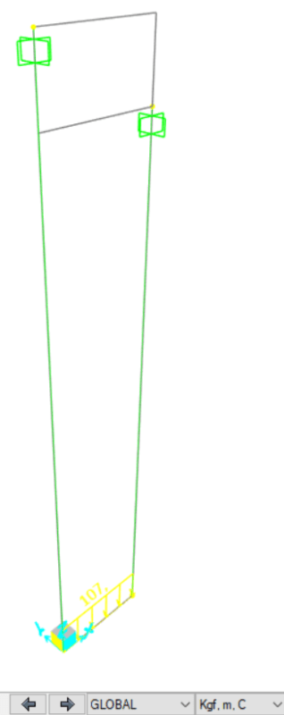
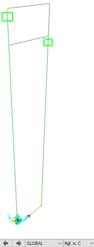
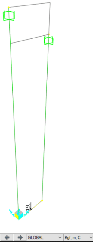
the program gives me various modeling warnings, and show me large displacement in the nodes.

How could you avoid being alert?

Operation : RUNNING ANALYSIS
Load Case : Solving Linear Stiffness from Zero (unstressed) initial conditions
THE STRUCTURE IS UNSTABLE OR ILL-CONDITIONED !!. CHECK THE STRUCTURE CAREFULLY FOR. TO OBTAIN FURTHER INFORMATION:. - USE THE STANDARD SOLVER, OR. - RUN AN EIGEN ANALYSIS USING AUTO FREQUENCY SHIFTING (WITH. ADDITIONAL MASS IF NEEDED) AND INVESTIGATE THE MODE SHAPES

*** Informational Message 1 ***
Date & Time : 27-12-2022 14:16:11
Run Tag : 0
Run Serial : 1
Operation : RUNNING CASES IN SERIES
Load Case : N/A
TOTAL TIME FOR THIS ANALYSIS: 00:00:00

*** Informational Message 2 ***
Date & Time : 27-12-2022 14:16:13
Run Tag : 0
Run Serial : 1
Operation : DELETING CASE RESULTS
Load Case : EX
RESULTS DELETED.

*** Informational Message 3 ***
Date & Time : 27-12-2022 14:16:13
Run Tag : 0
Run Serial : 2
Operation : RUNNING CASES IN SERIES
Load Case : N/A
TOTAL TIME FOR THIS ANALYSIS: 00:00:00


Thanks in advanced
 
Replies continue below

Recommended for you

Are the nodes at the bottom restrained in the X or Y direction? If not, then the model might be unstable.

Do you have a manual approximation that you can use as a sanity check? Generating one should be fairly straight-forward in this case.
 
I don't have a handmade calculation, i searched info about pendulum displacement, but i dont find an example with two cables in serie like the structure
 
You have vertical cables with a lateral load your model is inherently unstable. Cables only resist axial tension.

Mathematically your model appears such that it can experience unrestrained translation and unrestrained rotation in all directions.
 
Celt83 said:
You have vertical cables with a lateral load your model is inherently unstable. Cables only resist axial tension.

Mathematically your model appears such that it can experience unrestrained translation and unrestrained rotation in all directions.

this is an existent structure, used as support for power lines, spaced a 1.2 m.

There is a way to perform the calculation of displacements by hand?
 
You need to come up with appropriate nodal restraints for your analytical model in SAP, it does not appear that you have applied any currently (not clear in the graphics you’ve presented if any nodal restraints/support conditions are applied.)

A sketch of the actual structure may be helpful as well.
 
This is a drawing of the support
Drawing_lae1wa.png

* Fixed restraint
 
Teiko said:
I don't have a handmade calculation, i searched info about pendulum displacement, but i dont find an example with two cables in serie like the structure

Modify the model so that the two rods are the same length so that a textbook solution can be tested directly.
 
In the model, does the hanger section have a nonzero EI? Also, are there any releases in the model, such as moment releases at the ends of the hangers?

If the answer to both of those is "no" then I would expect SAP2000 to think the model is stable.

One more thing: Are you using a nonlinear analysis? The P-Delta analysis should be able to handle this by including the geometric stiffness of the rods in tension. The other option is Large Displacements -- that should work OK also. A linear analysis might think the horizontal displacement is huge, and maybe that would cause numerical issues.

I think you'll need a manual sanity-check to get a handle on this situation.
 
[link 271828]In the model, does the hanger section have a nonzero EI? Also, are there any releases in the model, such as moment releases at the ends of the hangers?

If the answer to both of those is "no" then I would expect SAP2000 to think the model is stable.

One more thing: Are you using a nonlinear analysis? The P-Delta analysis should be able to handle this by including the geometric stiffness of the rods in tension. The other option is Large Displacements -- that should work OK also. A linear analysis might think the horizontal displacement is huge, and maybe that would cause numerical issues.

I think you'll need a manual sanity-check to get a handle on this situation.
[/url]

I changed the horizontal beam to fixed, but the EI nonzero, i dont know how to changue it in cables.
With these changes, the model does not throw warnings, but it shows displacements of meters.

(I attached the model)
 
 https://files.engineering.com/getfile.aspx?folder=724c23fc-d5db-44c3-944c-6adb8ee0df65&file=MOD_-_2.7z
Am I missing something, or is this just two strings (which could be modelled as rods with a stiff-free condition) connected to a beam at each end (making the beam pinned-roller)?

If so, you should be able to determined vertical force and displacement in the string using just the 1D rod formula: EA(d^2u/dx^2) = b , where b=self-weight of string ("cable") per unit length. Boundary conditions would be "EAu(L)=F/2" and "u(x=0) = 0", where "F/2" is half the total vertical load on the beam and "x=0" is displacement at the fixed connection to the arch.

Lateral analysis can be done by assuming that the system consists of three beams with clamped connection to the arch and pinned (hinge, no moment) joints at the vertical-to-horizontal beam junctions. Easy to set up in a FEA program and doable also by hand.

You should not need cables for this model.
 
under a linear static analysis your structure is unstable with the hangers modeled as cables and a horizontal applied load. Cables only support tension, a horizontal load at the cable tray produces moment which needs to be resisted by a tension/compression couple, modeled as cables neither of the hangers can provide the compression component which makes the model fail a statics check.
 
You have a beam hanging in two cables. That means that it is more or less free to move horizontally and that probably explains the large deformations.

If you instead do it non-linear and include large deformations in the analysis you should be able to get the deformations more accurate. But that also means that you may have to rethink the seismic analysis.

 
ThomasH said:
You have a beam hanging in two cables. That means that it is more or less free to move horizontally and that probably explains the large deformations. ...

That's the way I see it. I don't think this situation even requires a computerized analysis. The rods are essentially inextensible and the bending stiffness is very low.

I think this is as simple as summing moments around the pin in the following figure, and solve for theta and lateral deflection. When I do that, I get about 2.4 m of lateral deflection. OP, how does that compare to your computerized result?

(Sorry for the figure size. I don't know how to change that.)

Hanger_Figure_xftyfz.jpg
 
271828 said:
I think this is as simple as summing moments around the pin in the following figure, and solve for theta and lateral deflection. When I do that, I get about 2.4 m of lateral deflection.

What is the basis for the forces (275 N / 186 N)? I think I am missing something.

Edit: Perhaps that comes from the attached file?
 
If I understand the SAP2000 screenshot units correctly, those are the 28 kgf and 19 kgf forces from the first post.

I just noticed the 107 kgf/m distributed load in the top diagram. I didn't include that in the diagram.

With it included, the method is the same. I get theta = 20.1 deg. and 977 mm lateral deflection.
 
@271828
If I understand it correct I think your approach may be valid as a "sanity check".

But the structure has little horizontal stiffness and the loading is seismic (inertia forces). To start with I think the masses should be modelled at their correct positions. But I can't help wondering how accurate this actualle needs to be. What is the purpose of the analysis? It seems that the OP is more into getting the model to run [smile].
 
As you have it shown and in your detail this is a vertical support only and offers no lateral restraint without seismic bracing. What exactly are you trying to check or design?
 
ThomasH said:
If I understand it correct I think your approach may be valid as a "sanity check".

Right. The main purpose is to help verify what's happening in SAP2000. It's easy to get tunnel-vision while trying to make the software work. The static structural analysis of this problem boils down to about two lines of manual calculations.

This design obviously has bigger problems because it has to do with seismic.
 
Maybe there's lateral stiffness somewhere down the line, as pipe racks tend to have. Like another bay that's braced with seismic cables or something. That wouldn't be captured in this model. As others have noted, I don't think this model is really analyzing anything. I'd design the support to be pin-pinned and calculate the axial forces in the cables.
 
Status
Not open for further replies.

Part and Inventory Search

Sponsor