Continue to Site

Eng-Tips is the largest engineering community on the Internet

Intelligent Work Forums for Engineering Professionals

  • Congratulations IDS on being selected by the Eng-Tips community for having the most helpful posts in the forums last week. Way to Go!

SAP2000 Share Force 2-2 and Reaction

Status
Not open for further replies.

MatevzStegnar

Civil/Environmental
Sep 17, 2019
8
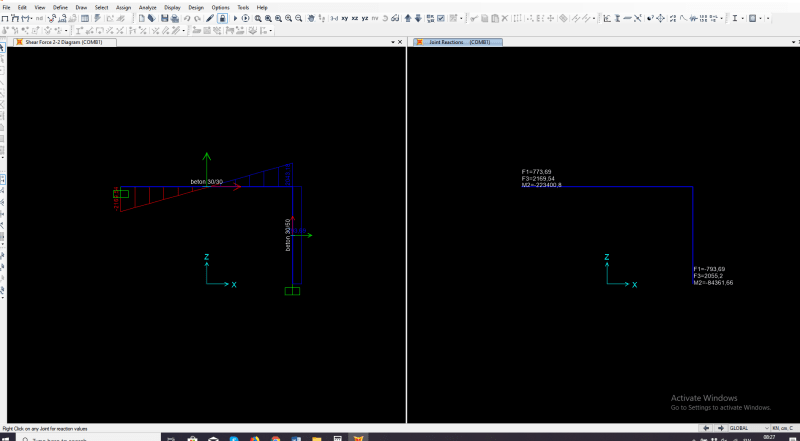
Have a question. Why shear force 2-2 diagram shows -0,91kN on column (local koordinates), first picture? But if i see reaction in global koordinate it shows F1=-0,91kN, second picture. According to this reaction shear force 2-2 diagram must be +0,91kN and not -0,91kN. I am confused now. Please for help. Thank you. Matevž
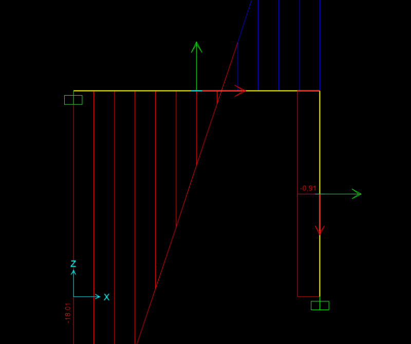
sap2_tkhsio.png

sap1_ox4kn4.png
 
Replies continue below

Recommended for you

Seems correct to me. Reaction is to the left, shear force diagram goes to the left from the point of support. Suggest you draw the shear force diagram from the reaction and you'll see what I mean. Rotate your column local coordinates if you want it positive, but I'll still be drawn on the same left side of the column.
 
From my prespective, reaction is to the left. But shear force is action and has opposite direction, which is to the right (positive in local coordinates). The same logic works in reaction of the beam. I understand your prespective but does not work in case of reaction of the beam. Thank you for replay.
 
For left beam reaction, reaction is positive (acting upwards), therefore shear force is negative. For example a small distance out from support, there is a small resultant load from UDL, sum forces in the vertical direction with positive reaction and you'll see the shear must be negative on the right end of the free body of the small beam segment. Think of it this way with a negative shear the positive reaction takes the shear back to zero (equilibrium).
 
Understand. But why this same logic does not work for the column support? Share force in small distance out of column support must be in right direction to equilibrium reaction which is in left direction. I am developing one simple logic that will work for every case and for every component.
 
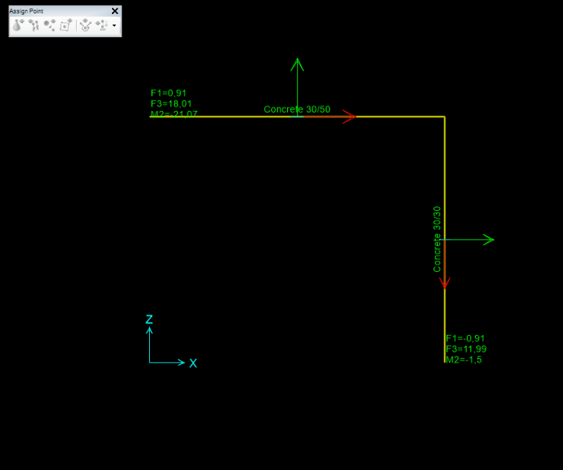
Now i get it. Start new testing frame, and the directions of reactions and shear forces work. Maybe the first frame has loads in y direction (global coorinates) becouse torsion (can not seen in pictures) is also appearing. Logic WORKS now.

sap3_swvesa.png
 
The second one has the 1-1 axis (the red arrow) reversed from the original pictures, that's the difference, the member is reversed in connectivity to nodes.
 
So what is your explanation on my question?

The side the design action is drawn on is related to the local coordinate system of the member, not the global coordinate system. If you want them all drawn on the "correct" side then maybe you always need to draw your members working left to right and bottom to top. If not sometimes the diagrams might not make sense and will seem counterintuitive, notwithstanding this the sign and value of the diagrams should be correct. It's more a visual thing.
 
I guess direction of active shear force in any element has no meaning of design element. But values does.
 
Status
Not open for further replies.

Part and Inventory Search

Sponsor