Continue to Site

Eng-Tips is the largest engineering community on the Internet

Intelligent Work Forums for Engineering Professionals

  • Congratulations KootK on being selected by the Eng-Tips community for having the most helpful posts in the forums last week. Way to Go!

Schematic for Fluke RPM80 Inductive Pickup (re: thread240-431670)

Status
Not open for further replies.

azchris

Electrical
Jul 13, 2022
2
thread240-431670
Regarding the previous (now closed) post:
"Sparkplug Clamp Pickup Sensor Circuit Fluke RPM80"

I found the thread discussing internals of the Fluke RPM80 pickup and there are a lot of photos but I didn't see an actual schematic.
I drew up what I think is the schematic but I wanted to confirm since I may have misinterpreted the photos
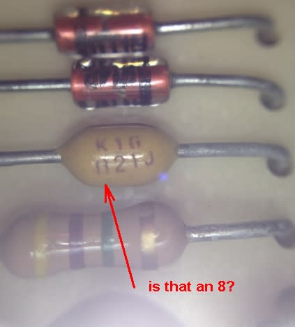
Also, I am not sure I correctly read the value of the Capacitor (does it say K1G / 821J ? I'm not sure I read the first digit (8?) correctly).
So I was hoping the original author of that post (MRSSPOCK) could comment... thanks!
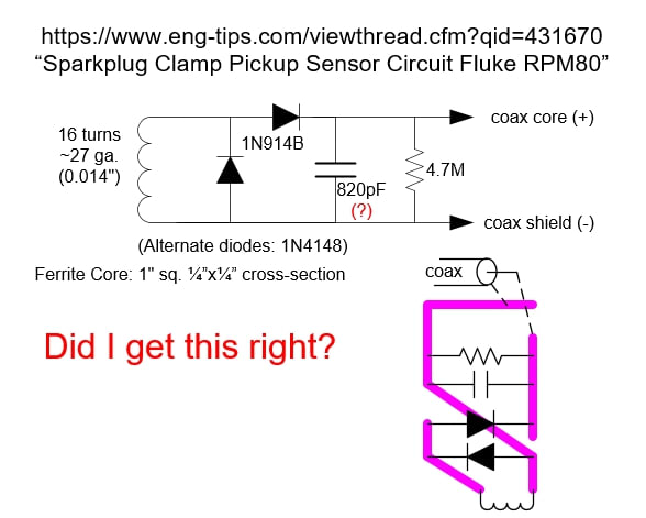
Fluke_RPM80_sch_udow6c.jpg
 
Replies continue below

Recommended for you

Schematic looks like what I would expect. One diode to put out a positive pulse and the diode across the coil to de-saturate (reset) the core when there is no spark. You gave the code from the axial capacitor as K1G821J where K1G means Kemet 100V COG, 821 means 820pf (a standard value) and J=5%. (I went to Digi-Key real quick and brought up a datasheet).

I looked at the picture and the core is a UI-core style with the winding on a leg of the U and the I on the clamp part to close the magnetic path. There are a number of different ferrites with different mu (permeability), so that is a minor mystery, but may not be too important.

The pickup is a transformer where the spark wire is a 1-turn input.
 
thanks for the feedback.
Yes the schematic looked reasonable and made sense to me as well, but
I could not read some of the photos clearly in the original post.
Especially the first digit on the value on the capacitor.
Coilcap_oizoa8.jpg


A few years back, I built an inductive pickup from part of an E-shaped, laminated iron transformer,
where I cut off one side, and I used the secondary winding and with a removable end.
I think it has something like 400 turns of wire.
I'm pretty sure the output voltage is much higher than I need.
So high, that I don't even need to connect both sides of the output coil to my timing light circuit
which has a 555-timer one-shot/pulse-stretcher which turns on a Triac to fire a trigger coil of a flash
I pulled out of an old Fujifilm disposible-camera.
So I might try this updated circuit for the front-end pickup.
 
Status
Not open for further replies.

Part and Inventory Search

Sponsor