Continue to Site

Eng-Tips is the largest engineering community on the Internet

Intelligent Work Forums for Engineering Professionals

  • Congratulations LittleInch on being selected by the Eng-Tips community for having the most helpful posts in the forums last week. Way to Go!

Scissor Lift Design Calculation 1

Status
Not open for further replies.

Munro23

Mechanical
May 2, 2017
2
Scissor_lift_sketch_qtq1tx.png


Hi there,

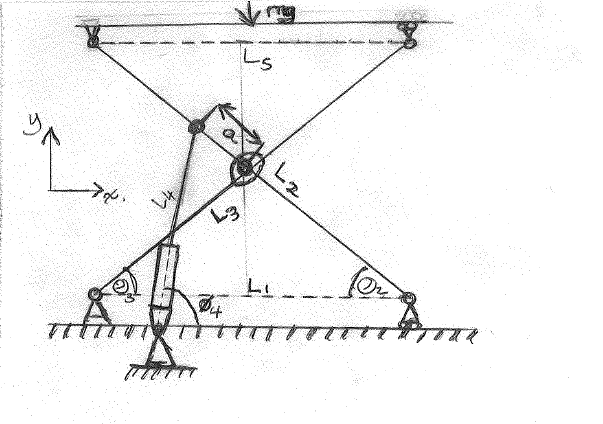
Could someone please help me. It's been many years since I've had to work something like this out and barely know where to begin with it. I want to understand the best position of the placement of the hydraulic cylinder. I realise my sketch doesn't include variables specifying the position of the fixed-to-ground/pivot end of the cylinder which is no doubt important. I don't know where to begin with a free body diagram. I realise also that I need to find all the Forces in the x and y direction for each node and the moments about them but I'm not sure about what role the centre pivot point plays in that. Also, I have stumbled across examples similar which show there to be a reaction force in the x direction at the point Ø₂, which just confuses me more as I would assume given that it is a roller, there will only be a reaction in the Y-direction.

If someone could give me some pointers to get me started, I'd be ever so grateful.


Thanks.
 
Replies continue below

Recommended for you

The "best" location is for the cylinder to push the top plate straight up. This would require a pit to place the cylinder, so obviously other constraints must be considered. Only you know your constraints at this point.
 
I'd start with "work done". Work done by the actuator is "easy", P*dx. Then if the actuator extends dx, this'll lift the table (weight) dy, ie work done by actuator = work done by weight. This'll allow you to evaluate different actuator positions; I thought it was common to have a horizontal actuator. Then I'd start sizing the members (with a FBD).

There are many threads on scissor lifts, but they may confuse more than they help !?

I'm sure there are google and wiki references as well.

another day in paradise, or is paradise one day closer ?
 
Good job; one of the best sketches I have seen in eng-tips.com.
 
Sorry, maybe its me, but this doesn't look right. Can you define on your drawing which pivot is fixed and which is moving

Remember - More details = better answers
Also: If you get a response it's polite to respond to it.
 
Thanks for your inputs so far...

Apologies for my sketch and what it is missing. I should mention that this is already a built design that I am working on and the layout already exists. I am trying to find out first how to solve the problem of what the initial force required for a given load will be when the cylinder is in its retracted position and the top plate-(which remains level when raising up and down, with the force "mg" acting on it)- is in it's lowest position to get it rising. Obviously the more horizontal the cylinder is the less upward force there will be. (This is what I ultimately want to change, the initial angle position of the retracted cylinder but I want to do so by calculation first)

The cylinder is fixed at both ends but is pinned in place, at both ends, allowing it to pivot as it retracts and extends.
The Top plate (with load on) is able to travel up and down, the movement enabled through the scissoring action of the two lengths which I've not so clearly marked L3 and L2.
At the fixed point with the angle showing Ø3, it is fixed in the x and y directions but can also pivot.
At the fixed point with the angle showing Ø2, it is able to translate in the x direction, pivot, but is obviously unable to move in the y-direction.
The main scissoring pivot is about the centre point. This is one of my main stumbling blocks as I am uncertain how to show the reactions of this in free body diagram form.

I have failed to mark out angles at the top-plate connections but is basically a mirror image of the bottom (having a roller connection on top right). I am sure the angles Ø3 and Ø2 will equal these top angles.
The lengths marked L1 and L5 are not part of the structure they are just showing the distance between the points.

Thanks again for all interest shown
 
Energy in = energy out. If the cylinder extends 0.05 inches and the platform moves 0.10 inches then the force in the cylinder will be twice what the load on the platform is. This method doesn't include friction under load at the various pivots, but it does give a good first approximation.

This is what rb1957 was getting at.
 
this is theory (you can watch the video of FEA analysis) : if you need help for translation please tell me


L’idea del pantografo : the idea
Analisi cinematica : cinematics
Analisi della struttura : structure analysis
Dimensionamento travi : beams calculation
Scelta attuativa : choice for movement (two hydraulic jacks instead of only one)
Analisi ad elementi finiti : FEA analysis
Modello definitivo : final design
 
It might be beneficial to attach the actuator at the lower vertex (shown at angle ø2) instead at the point marked by dimension "a".
The attachment at "a" causes bending in the lift's supports which they don't need, and it has very little mechanical advantage when the lift is near full extension.

The lower attachment of the actuator, just below the plane of the lower supports, seems suitable. By attaching the actuator to the lower left pin (ø2) you also gain mechanical advantage as you lift, not lose it.

Thank you for the very clear free body diagram! If only every question included a diagram such as yours.

STF
 
"(shown at angle ø2)" ... don't you mean "ø3", unless you move the upper attmt to the other leg

another day in paradise, or is paradise one day closer ?
 
Yes, indeed, the base of the actuator could be attached at ø3 or the lower attachment (ø4), both would work. From there attach the rod to ø2, in either case.

STF
 
If you were to study commercially made scissor lifts, the answer is in plain view and has been suggested above.
 
Status
Not open for further replies.

Part and Inventory Search

Sponsor