Eng-Tips is the largest engineering community on the Internet

Intelligent Work Forums for Engineering Professionals

Scissor Truss Concealed Connections

Status
Not open for further replies.

m_struct

Structural
Nov 11, 2020
64
0
6
NZ
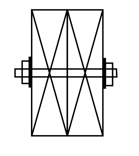
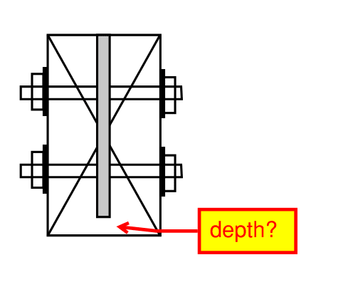
A client has decided against the external plate connection for a timber scissor truss and has requested concealed connection for the 90mm (3.5”) wide members.

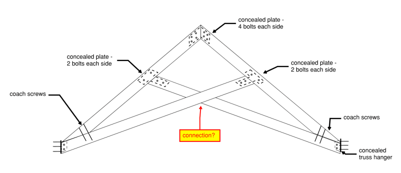
What type of concealed connections are typically used for these truss? I was considering about plate connections for the top three connections, coach screws for bottom/chord connections. How are the bottom chords detailed where they cross? Note the truss is not very heavily loaded and is more decorative. Also, is there a rule of thumb of where the bottom chord should ideally insect the top chord - like mid-point?

Scissor_Truss_xqqwmr.png
 
Replies continue below

Recommended for you

Never seen a concealed hanger used on a scissor truss. Might be possible. Might even be easy. I don't know.

The crossing of the bottom chords in a timber truss is often accomplished with a half lap - cut a notch out of each that goes half the depth of the member - and fasten them together.

Where the bottom chord and top chord intersect will be a function of the difference in pitch of the two chords, nothing more. Then it's just a matter of sizing the members for the resulting load effects.
 
Not sure its a good idea to connect the crossing members as shown. Doing so will induce (unintended??) moments into the crossing members and negate the classic truss analysis assumption of only having axially loaded members.
 
MotorCity - that's how it was done in old timber scissor trusses (and in new ones that people are still willing to pay for from specialist manufacturers and craftsmen). The 'classic' truss analysis of axial only members is mostly a fantasy anyway. Some bridges and truss girders maintain it, but I've never seen any other truss that fit that model. Standard roof and floor trusses, open web steel joists...they all have members in bending from external loads.
 
I've designed plied trusses like this using split ring connectors :D. I would have preferred metal dowels, but I was in heavy snow country and had to use split ring connectors. None of the guys I worked with (or the builder) had ever used them. But I spent a lot of time getting to know them and so did the carpenter and things turned out really good. You can look into just smooth dowels for your connectors they are easy to conceal and there is growing literature regarding their use. I am with @phamENG on this one reg'd trying to force the truss to axial only, its not common in homes, there should be no problem for decently proportioned wood members to carry some bending and axial.

You could use a knife plate with through bolts that are recessed, however to get them totally conceleed you'd probably need to countersink them so far that there is nothing left.

THis is why the dowel pins are useful. [URL unfurl="true"]https://www.youtube.com/watch?v=wPgONhvd6Lg&ab_channel=CivilEngineeringRWTHAachenUniversity[/url]
 
is that sketch one of the Escher things ... lines show overlapping members ?

are all four elements meant to be in the same plane ??

could you not route a slot in adjacent elements and use a steel plate to join ? use proper bolts with the heads and nuts in counterbores, and fill the counterbores with wooden pegs ?

another day in paradise, or is paradise one day closer ?
 
Thank you for the input.

All the members are in the same plane. If cross members are notched, they would look like
Cross_members_vakma0.png


I thought about using a concealed plate at the junction of the bottom chords and you like to be do what is more practical. Notch vs concealed plate?

In terms of constructability, would 90mm (3.5") wide members, with 45mm each at the cross members, be sufficient width? Or should I be pushing for 100mm or 140mm. If the bolts are concealed and plugged, how many depth is required for the plug hole?

The client would not like to see the concealed plates from below. For the concealed truss hanger, would a partial depth (say all but 15mm) or would a full depth slot be cut and then piece of wood glued in place or base. What minimum depth are you looking at?
Concealed_Truss_hanger_k8namb.png
 
You client needs to realize that if they are going to use the wrong tool for the job, they are going to get the wrong results. A metal plate connected truss (pressed plates from a truss factory or bolted plates as you're discussing) is not going to look like a plate/bolt free timber truss.

What they need is not a general structural engineer such as you or me; they need a company that specializes in the fabrication of custom timber trusses. These can be built with some fantastic joinery with nary a piece of metal near them. It's not easy. It's not cheap. It is an absolute work of art. If that's what they want, they need to go to one of those companies and have it designed and built. If this is a small portion of a structure you're designing, you need to specify the requirements and let the contractor buy it as a package with a deferred submittal.

You could try to design it with the joinery, but you should probably do it on your own time and for fun - it's not an easy analysis if you've never done it. And if you don't know the joinery, you'll be wondering around in the dark for days until you find enough information about how it can be done, and then when it gets built you'll find out how the carpenter does it and you'll either have to change your design or change your carpenter.
 
Very good point.

All the members acting with axial loads (tension/compression) with some minimal bending in the top chord.

At the top/bottom chord junction - you mentioned "sizing the members for the resulting load effects". Are you referring to at moment caused by an eccentric load put on the bottom chord?
 
These are largely questions for the fabricator. One needs to know what equipment you have and how many are needed. These type of details can easily triple the cost of the parts, and few owners understand that. We work with one fabricator that has a $2mil milling machine for this type of work. When it is fired up it is not $30/hr, and it requires a lot of information before it does anything.
 
Make the truss three plies thick. If it is not heavily loaded you should be able to make it work with overlapping wood shear connections.
 
if all the elements are in the same plane, what happens at the flagged intersection ?

could you do some "artistic" mortise joints ?

another day in paradise, or is paradise one day closer ?
 
@m_struct I saw this guide posted by Enable on another thread. Interesting page on the scissor truss that you might find useful. When I first saw your sketch something from way back in statics was pinging around in my head. You have a 4-sided shape in your truss, which essentially is going to require Vierendeel truss action. This truss badly wants a king!

[link Link]https://dcstructural.com/wp-content/uploads/2020/09/TFEC-4-2020-Design-Guide-for-Timber-Roof-Trusses.pdf[/url]
 
Status
Not open for further replies.
Back
Top