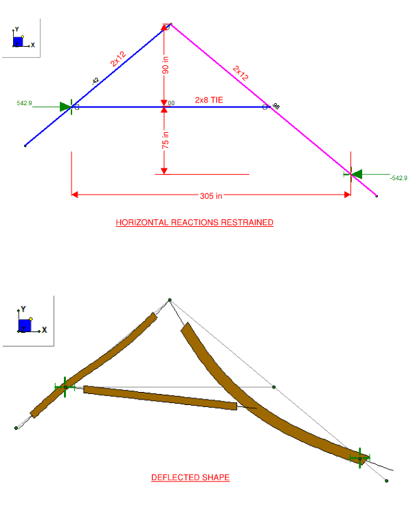
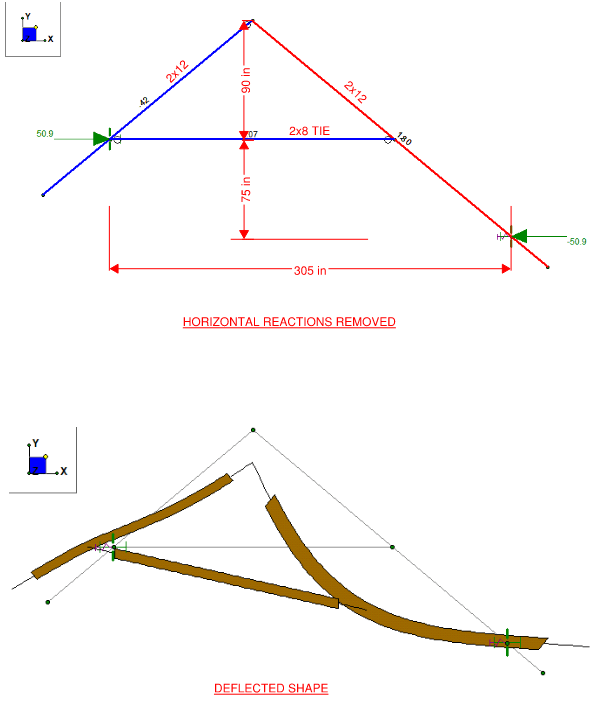
I am designing a small wood structure (barn), and the roof structure is similar to that of a scissor truss concept with kickout forces and I am looking for advice on how to analyze the scissor type framing correctly. For this discussion the geometry of the framing and boundary conditions can't change, so no the collar tie can't be located at the bearing. I've provided dimensions only for reference but am looking for the correct way of analysis scissor truss type framing. In the imagines, you'll see the framing is rafter's with a ridge beam and a sort of collar tie across to the rafters. The rafters will be bearing on a wood stud wall each size of the truss, which is where I show the boundary conditions.
In the first imagine, I've showed the method of restraining the horizontal reactions, which means I am counting on the wall to provide that rigidity. You'll also see the member utilizations of the members and the deflected shape (it is shown as magnified for this discussion). Because the frame is restrained horizontally at the bearing and thus not deflecting by kickout the member utilizations are within allowables - though close to unity.
The second image is the horizontal restraints as essentially nothing (very light springs), resembling the wall to not provide the stiffness and restrain the horizontal kickout. Thus allowing for the deflection to happen within the wall and roof framing. In this method, allowing the deflection to happen, the member utilization is way over unity due to the collar tie happening along the length of the one rafter. This is creating a high bending stress in the member.
My question is which approach is the correct approach. Consider the wall as restraining the kickout? Or allowing the kickout and deflection (within allowable deflection ratios) and sizing the members appropriately for the forces.
My thought is, how could you consider the wood stud wall to provide that rigidity? This would result in a shear at the top of the wall, creating an overturning moment at the base - which would be impossible to resolve. I'm thinking you have to allow the deflection, but limit the deflection to be within allowable for the building material and then size the roof framing members for the subsequent forces. I look forward to the discussion here and thank you very much in advance!


