Continue to Site

Eng-Tips is the largest engineering community on the Internet

Intelligent Work Forums for Engineering Professionals

  • Congratulations IDS on being selected by the Eng-Tips community for having the most helpful posts in the forums last week. Way to Go!

SCR faults on DC Drive 5

Status
Not open for further replies.

lukin1977

Mechanical
Jan 19, 2009
397
Situation:

A 9 blocks wire drawing machine. Each block has one 12,6 kW DC Motor. Each block has one DC Drive for each motor. All the motors and drives are equal.

DC Drive on block 4 is having a repetitive fault (4 times in one year). 2 SCR bridge tyristors on the drive explote (see picture).
We checked motor and block`s mechanical many times and never found anything wrong so I am suspecting that there is happening something from the drive`s input side that is damaging the SCRs.

What can be causing this? What things should I check from drive`s input side?
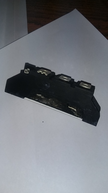
20160601_132822_p2oj0n.jpg
 
Replies continue below

Recommended for you

After the 2nd fault I installed a new Drive and same fault again. Last time it only blown one of the 3 SCRs
 
I would have a detailed look at snubbers and commutating reactors.

Snubbers need to be checked for R and C values as well as wiring integrity.

Commutating reactors: Check voltage drop at load. It should be the same (give or take 10%) for each individual reactor.

Also, check arcing at full load. If there is bad arcing, you have to find the reason and remedy.

Gunnar Englund
--------------------------------------
Half full - Half empty? I don't mind. It's what in it that counts.
 
dV/dt is one of usual suspects, aka "line spikes" that cause the SCRs to self commutate (fire) when they are not supposed to. I find a big culprit for that is nearby open transition Wye-Delta motor starters. People often use them with no concern for what they can do to other equipment nearby, especially anything with thyristors. I once had a meat plant that experienced multiple failures in succession and they swore it was nothing at their site. We put a Dranetz recording meter on it and sure enough, there was a huge spike right at the time units failed the next time. Then by looking at their process and the time of day, we found a separator that had a 4 speed motor controller that used open transition Wye and Delta changes in a complicated system involving something like a dozen contactors. It was one of the most convoluted systems I'd ever seen, made in Germany in the 50s. They had no idea it was even like that. The spike it threw out into the line every time they changed speeds were often as much as 2,000V. Not every time, but some times, likely due to differences in phase angles at the exact moment of transition.


"You measure the size of the accomplishment by the obstacles you had to overcome to reach your goals" -- Booker T. Washington
 
What Jeff says is definitely true. But, if there are nine blocks and only one fails.I think that it is easier to do a quick check on the block that fails. A mains transient very rarely hits just one drive. Snubbers and commutating reactors are there to prevent high dv/dt (from internal turn-off recovery and commutating transients) so Jeff's observation that du/dt can kill makes it even more interesting to check them out thoroughly.

That twelve-contactor contraption from the fifties is a typical example of the philosophy* that we found so many examples of back in the older days.

*"Warum einfach, wenn mann es so schön komplizieren kann" (Why keep it simple when it can be so beautifully complicated).

The Americans kept it simple, and working. Fewer and easier-to-handle problems in their equipment.

Gunnar Englund
--------------------------------------
Half full - Half empty? I don't mind. It's what in it that counts.
 
Hmmm, yeah I missed that it was the same unit failing repeatedly and only that one. I agree then, likely a bad snubber board for that unit. Without snubbers they will work for a while, but failure is inevitable. I forgot that when I wrote ownersanuals for soft starters and power supplies, I always included the warning to replace snubbers whenever replacing SCRs, because often the same event that damages an SCR also damages the snubber, but it's difficult to tell.

Gunnar, when I worked for Klockner Moeller back in the late 70s, that, or something like it, was a favorite saying among the Germans who we worked for. I had forgotten it, thanks for that!


"You measure the size of the accomplishment by the obstacles you had to overcome to reach your goals" -- Booker T. Washington
 
There are no snubbers and no input reactor installed
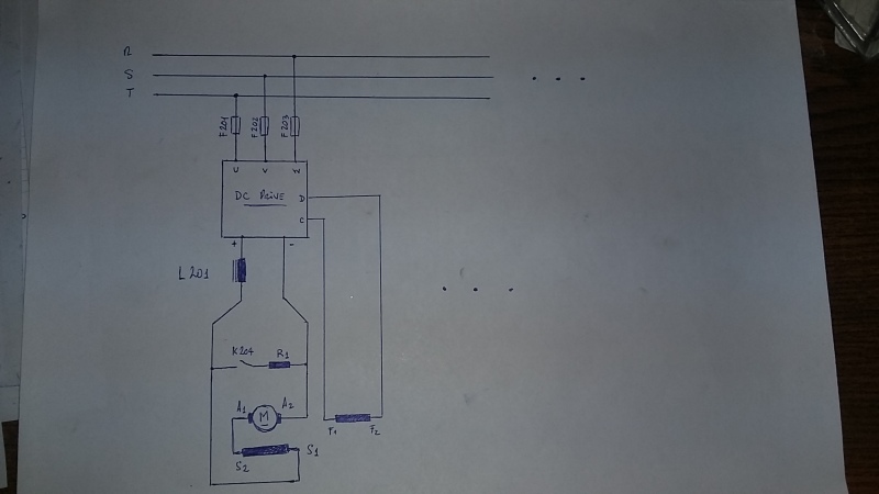
Please see the schematic drawing I made.
L201 output reactor 18,5 mH
R1 Brake resistor for emergency stop
K204 Emergency stop contact
F201, F202, F203 input fuses

All 9 Drives are feed the same way from R-S-T Bar but only Block 4 keeps failing

Can loose terminals on fuses connection be causing the fault? I am not saying we found that, just asking
What about a mistiming between K204 and Drive Disable operation?
Skogsgurra: Are you meaning to arcing on motor commutator? We have checked this many times while in operation. There is not abnormal arcing

20160602_104302_lpfuar.jpg
 
My first thought also. Take a good look K204, R1 and all the associated wiring and connections.
Another option may be to swap the motor with one of the other motors and see if the fault follows the motor or stays with K204.

Bill
--------------------
"Why not the best?"
Jimmy Carter
 
K204: Will check that too. The thing is that the fault occurs while the machine is running not when braking
About swapping motors. Already done that. Fault stays on block 4
 
Please investigate also the cabinet temp of block 4. If you have 9 of them, no. 4 should be in the middle of a row! Just a hunch though.
 
flexoprinting: I dont think that the cause of the fault is internal to the Drive. Like I said before, we installed a new drive and same fault occurred

Next week I will be checking K204 and connections from input and output of drive


I have a feeling that you want a discussion, where you win, instead of a solution to the problem.

There is not much need to check the braking resistor and the contactor. If the contactor is closed most of the time, the resistor gets hot - which you will notice - and if it doesn't close, all that happens is that you can't brake, which the operators would notice and alert you.

So, forget about that.

My suggestion (1 Jun 16 21:01) to check snubbers and commutating reactors were turned down because there were no such things (snubbers and reactors). Lukin, flexoprinter and parchie have all contributed with facts that you also turned down as irrelevant. I do not understand why you ask for help and then tell us you don't need it or that the ideas are wrong. Cannot understand that at all.

Facts:
There are snubbers, flexo actually told you where to find them.

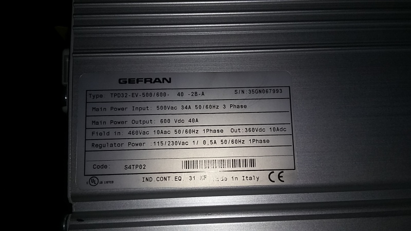
Figure 4.8.3: "Typical connections" shows that there should be commutating reactors. The L1 in the diagram.

Parchie notes that block 4 probably is in the middle of the cubicle, so temperature may be high.

Now, add these contributions and what do you get?

1. Commutating reactors are there to keep di/dt below maximum allowed value. If you don't have them, the thyristors will overheat locally due to time needed to spread the conduction zone across the Si crystal.
2. Heat kills.
3. If ambient temperature is higher for drive #4, which Parchie suggests, then the drive with the highest temperature fails.
4. Now, which drive fails? Is it number 4? Is that a coincidence? Or can you accept that heat and absence of the necessary commutating reactors may have something to do with the failure?

Just askin'


Gunnar Englund
--------------------------------------
Half full - Half empty? I don't mind. It's what in it that counts.
 
I dont want a discussion where I win. I respect all of you very much and I am very thankful for your help. I am just saying what I think and trying to reply to all the suggestions made

I forgot to answer Parchie`s suggestion about the middle position of Drive been the problem. Sorry about that, but, that is not the case. (again, not trying to win anything)

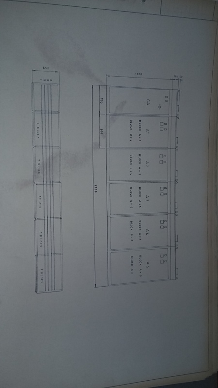
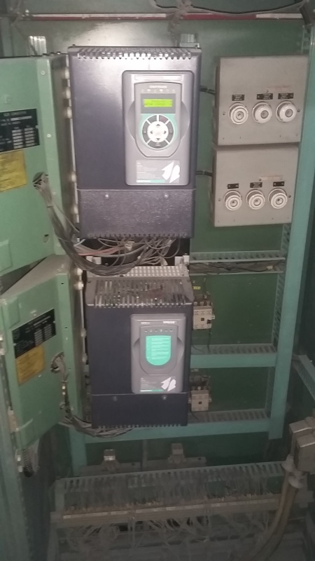
The 9 drives are installed in pairs inside individual fan ventilated cabinets

1st cabinet: Command circuit and logic components
2nd: blocks 1 and 2
3rd: block 3 and 4
4th: block 5 and 6
5th: block 7 and 8
6th: block 9

Non of the 9 drives have input reactors installed. They only have one reactor at the output side. L201

How do I check if output reactor (L201) on block 4 is fine?

Thanks!

20160606_090255_j8znxk.jpg


20160606_090443_efsknq.jpg
 
There shall be commutating reactors. They are shown in the manual. Failing thyristors are typical when commutating reactors are ignored. It is not only ambient temperature, but also current drawn that determines if thyristors fail or not. Fast fuses do not protect thyristors if there isn't any commutating reactor.If you are serious about this, then measure di/dt and compare to the thysistor's specs. People make mistakes and I have seen that on refurbished Arboga machines where Philips drives were replaced with new ones.

The DC reactor cannot make the thyristors fail. It is there to reduce armature current ripple. Arcing in the motor is typical if there is a problem with the DC reactor. Many drives are fine without one. But not without commutating reactors.

You do not need to check the DC reactor. But if you really want to, a bad DC reactor is either burnt or mechanically defect. That latter, I have never experienced. It is also possible to check a DC reactor with a car battery and see if it reacts like a reactor (current increasing according to 1- exp[-t/T]). You can also apply an AC voltage and calculate L from current and frequency. An RCL bridge seldom works when used on heavy reactors, frequency is usually kHz, which is too high to measure a DC reactor. But don't bother about that. The DC reactor is not the problem.

Gunnar Englund
--------------------------------------
Half full - Half empty? I don't mind. It's what in it that counts.
 
OK. Thanks
Machine is now in operation but only using blocks 5 to 9. I measured voltage drop on DC reactors of the working blocks while in operation and they all read 1 V +/- 0,5 V

I understand the importance of commutating reactors but the situation is like it is, and there is no way that we can install the reactors in all the blocks at the present moment.

By the way. This is an Arboga machine with new drives [smile]

Can loose terminals on fuses connections be causing the fault? Fault is happening only on block 4
An AC input choke is a commutating reactor?
 
Loose connections are never good. Don't speculate. Tighten them.

Gunnar Englund
--------------------------------------
Half full - Half empty? I don't mind. It's what in it that counts.
 
Status
Not open for further replies.

Part and Inventory Search

Sponsor