Continue to Site

Eng-Tips is the largest engineering community on the Internet

Intelligent Work Forums for Engineering Professionals

  • Congratulations IDS on being selected by the Eng-Tips community for having the most helpful posts in the forums last week. Way to Go!

SCR faults on DC Drive 5

Status
Not open for further replies.

lukin1977

Mechanical
Jan 19, 2009
397
Situation:

A 9 blocks wire drawing machine. Each block has one 12,6 kW DC Motor. Each block has one DC Drive for each motor. All the motors and drives are equal.

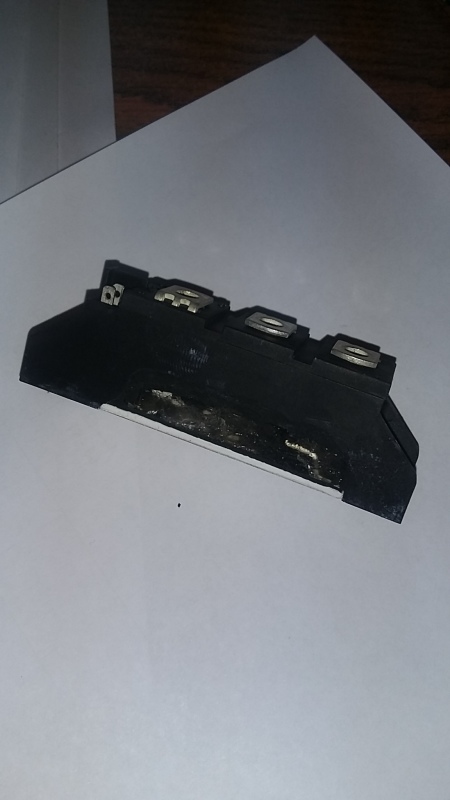
DC Drive on block 4 is having a repetitive fault (4 times in one year). 2 SCR bridge tyristors on the drive explote (see picture).
We checked motor and block`s mechanical many times and never found anything wrong so I am suspecting that there is happening something from the drive`s input side that is damaging the SCRs.

What can be causing this? What things should I check from drive`s input side?
20160601_132822_p2oj0n.jpg
 
Replies continue below

Recommended for you

I checked all the terminal connections in cabinet. Nothing loose
Will be installing AC reactors on block 4 ASAP. This will the first time I have to select AC reactors. Any help please? Local companies around here do not help at all
 
Fine! I like that.

For the prudent, select a reactor that drops around 4% at rated current. For the more adventurous, select one that drops 2%. If these drives run without reactors now, I think that 2% drop will be sufficient. It usually is.

Percent drop of what? Good question. When you run at rated current, the drop measured over the Reactor shall be 2% of applied L-N voltage. In your case, 500 V in and 34 A rated, will need reactors that drop around 10 V at 34 A. RMS in both cases. So, X is 14.7/sqrt(3) = 8.5 ohms. That corresponds to around 13 mH at 50 Hz. Never mind the different waveforms. Just go RMS, everyone else does. Expect delivery of a unit weighing around 5 kg, give or take a few kgs.

Gunnar Englund
--------------------------------------
Half full - Half empty? I don't mind. It's what in it that counts.
 
Thanks Skogsgurra!
Mains voltage is 3x380V
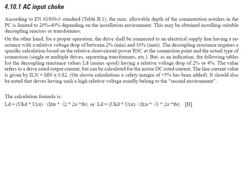
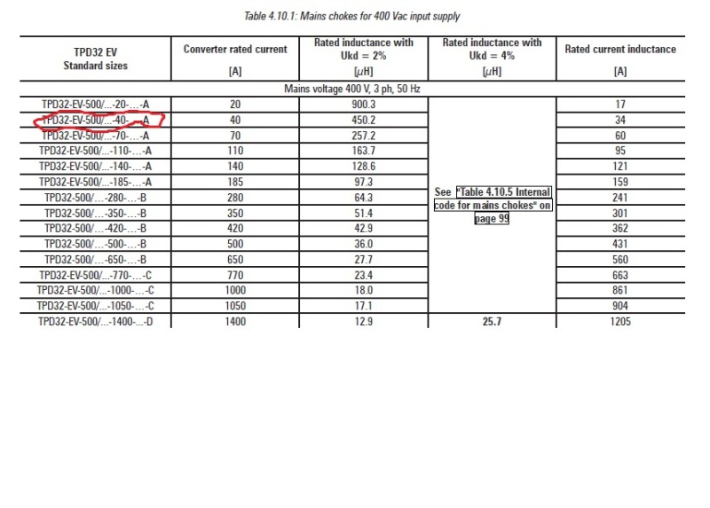
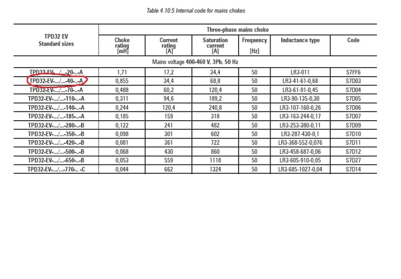
I have the DC Drive TPD32 EV Instruction Manual and this is what I found:

AC_choke_1_nce0ls.jpg


AC_choke_2_tkvn2e.jpg


AC_choke_3_lhv8kw.jpg
 
Sorry to bother you again but,
How did you calculate L from 8,5 ohm?

XL=w.L=2 x pi x f x L=2 x 3,1415 x 50 x L

8,5=100 x pi x L

L= 0,027 H

L=27mH
 
I used a slide ruler. Use your value if you feel more comfortable with it. Any reactor in the right ball-park is better than no reactor at all. You were most unwilling to put any reactor there only yesterday - remember? Use anything that isn't ridiculously small or large.

Gunnar Englund
--------------------------------------
Half full - Half empty? I don't mind. It's what in it that counts.
 
I wrote to Gefran for a quotation for the reactor code S7D03 . What still puzzles me is why only block 4 keeps falling

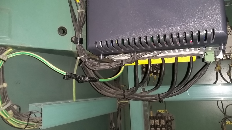
The only suspicious thing that I found different from the other blocks is a joint in the PE cable to the drive. See picture

20160607_114929_znclr4.jpg
 
You can also opt to put in one larger reactor for each pair of drives if there is a single feed to them, that might make it easier. Same inductance, but sized for the total current of both motors.

Another thing that might be happening here is relating to that K204 contactor again. Your sketch doesn't show the control circuit, but assuming that contactor is controlled by an output of the drive, and assuming you tapped L-N for 230V control power, it would be IMPERATIVE for the coil of that contactor to have surge suppression. It could be that in all of your cabinets, the contactor coils did have surge suppression installed initially, but on this particular unit it has burned out, allowing a spike to get back onto the AC line every time that contactor changes state. Distance of the circuit may be preventing that spike from causing self commutation in any adjacent drives, but because it is right there on #4, it affects only that one and because you likely left that contactor in place when you swapped out the drive, you killed the replacement eventually too.


"You measure the size of the accomplishment by the obstacles you had to overcome to reach your goals" -- Booker T. Washington
 
Can you swap components to see if the problem moves to another motor or block?
 
Need to apply 2-4% factor, so L will be about 0.5 - 1mH.
 
There might be a problem with L201. This may have been placed in the circuit to limit di/dt. If current rises too fast through a SCR, device damage will occur. Inductors in either the AC side or the DC side will lower the current rise.
 
Dear iop, there you go again.

Gunnar Englund
--------------------------------------
Half full - Half empty? I don't mind. It's what in it that counts.
 
dja
A reactor in the DC side does NOT reduce di/dt. Only AC reactors do. Have a closer look at the commutation between thyristors and you will understand why.

Gunnar Englund
--------------------------------------
Half full - Half empty? I don't mind. It's what in it that counts.
 
BrianE22. Yes, We already tried that. We swapped motors and problem stayed in #4. 3rd time it failed I installed new DC Drive also failed after 2 weeks of operation. On previous fails I changed the drive`s 3 SCRs with identical spares (IXYS MCC26 - 16IO1B - ND)

jraef:
Good idea about a single reactor for each cabinet. Thanks!
yes, control circuit is 220V

I will try to explain the logic of the ES (emergency stop) control circuit

On each wire drawing block there are emergency push bottoms that are series connected. When one of them is pushed it closes a relay in cabinet Nº1 (relay GA.K11). This relay close a contact that goes to all of the rest of the cabinets. ES signal

On each cabinet there is another ES relay (A.K1) that opens drive´s enable signal and closes K204 (brake resistor contactor)

Normal operation:

There is a ramp generator card on cabinet 1 that feed all the rest. When start bottom is pushed the drives are enabled and ramp goes up. When stop is pushed ramp goes down and enable signal is cut off BUT there is an programable relay contact on each drive (Relay 2) that is used to keep each drive enable until speed gets down to a certain low value (speed zero level)

I been taking to machine operator and he told me that he never uses the ES while at full speed but he uses to stop the machine while he is in threading stage (this is when the wire is pulled from block to block until 9th at low speed) because is easy for him to push the ES than the normal stop bottom. So on each day ES may be pushed many times

I think this relay 2 is causing the K204 to close while drive is still enable. This is what I was referring to on 2 Jun 16 14:53 when I said: mistiming between K204 and Drive Disable operation

Will have to check the speed zero level on relay 2 on drive #4. They are not the same on every block due to different speed reducer gears

Also checked for surge suppressors and there are none. Will have to install them too
 
Status
Not open for further replies.

Part and Inventory Search

Sponsor