Continue to Site

Eng-Tips is the largest engineering community on the Internet

Intelligent Work Forums for Engineering Professionals

  • Congratulations KootK on being selected by the Eng-Tips community for having the most helpful posts in the forums last week. Way to Go!

Searching for simplification of material properties 1

Status
Not open for further replies.

LCform

Mechanical
Jan 13, 2016
139
Hi All

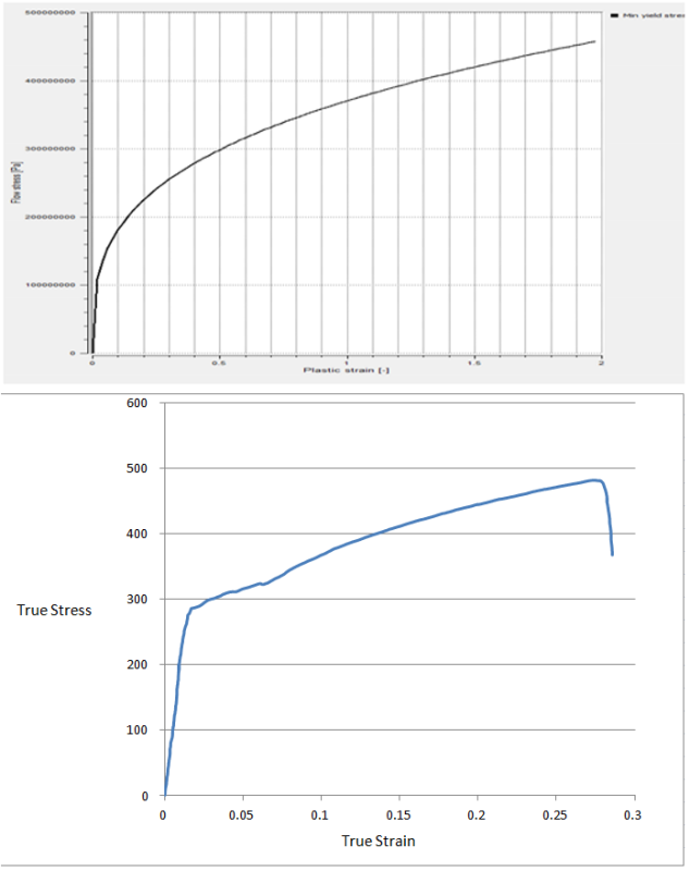
I am doing some metal forming (cold) analysis, for that , my material properties can only be inserted in a simplified way. that is : sigmaf = C*(fi)^N

After tensile test, I noticed differences between the real material and the one in the FEM model ,since I can not model the real one, I would like to ask you , do you think there is too much difference between the two ?

the upper photo attached is the one in the software, and the lower is the one from the tensile test
material_prop_simplification_dcuoni.png
 
Replies continue below

Recommended for you


Thank you Aero, but not exactly , maybe fatigue will be my next concern , so I will study this post well , here the material is steel, but you see, this kind of material representation, makes it behave like aluminum ,no ? for me, this problem pops out for example in extrusions , I get a bit longer lengths of deformed material than expected. like 1 mm in every 10 or 20 mm length
 
Did you input the curve correctly in the software? The real test data says, true strain. The software says plastic strain. Plastic strain curves usually start from the yield point.
 
As gravityandinertia suggests one has to compare the two on same basis.
Probably the easiest is to digitize the tensile test figure. A download
program "engauge" works well though on some versions one has to change the
colors to black.
In a spread sheet then compute the Emodulus= Stress/Strain in elastic region.
Then compute the plastic strain = total Strain - Stress/Emod
Then plot it on the same figure that shows your stress vs plastic strain.
Just for fun I did the digitizing:
[pre]
Using E=21000 (?)
Strain Sts CompE PlasticStr
0 0 0 0.0
0.00066 25.8 39017 -0.00057 (make -ve Plas Strs to zero)
0.00258 50.0 19342 0.00020
0.00325 80.3 24709 -0.00057
0.00517 96.9 18767 0.00055
0.00583 122.7 21062 -0.00002
0.00712 150.0 21062 0.00000
0.00843 189.4 22468 -0.00059
0.00971 206.0 21214 -0.00010
0.01036 225.7 21776 -0.00038
0.01164 237.8 20425 0.00032
0.01229 251.5 20459 0.00032
0.01357 262.1 0.00109
0.01421 266.6 0.00151
0.01421 272.7 0.00123
0.01612 280.2 0.00277
0.01739 284.8 0.00383
0.02056 287.8 0.00685
0.02372 290.8 0.00988
0.02690 296.8 0.01276
0.03196 301.4 0.01761
0.03640 305.9 0.02183
0.04083 308.9 0.02612
0.04400 311.9 0.02915
0.04717 313.4 0.03224
0.05287 319.4 0.03766
0.06047 323.9 0.04504
0.06363 322.4 0.04828
0.07694 339.0 0.06080
0.09912 366.2 0.08168
0.11813 385.8 0.09976
0.13903 403.8 0.11980
0.16247 420.4 0.14245
0.18844 436.9 0.16763
0.22137 454.9 0.19970
0.26063 474.4 0.23803
0.27519 480.4 0.25231
0.28025 475.9 0.25759
[/pre]
Seems like an odd material. Elastic to 0.01 Strain??
You might want to do a units check at the tensile machine. :)
 
sorry, and thank you very much for your kind attention , It seem I made a bad mistake, so the stress at the begining is not actually zero and refers to post yield ?

I got the tension results as force displacement, at converted them myself , you can find them attached

 
 http://files.engineering.com/getfile.aspx?folder=c05ce6d8-e8c9-4204-8cda-79531e75281d&file=data_digitized-dia5.xlsx
Seems like an odd material. Elastic to 0.01 Strain??

well or I have mistaken the digitizing, or it's the problem you mentioned , cause it's not done on a machine with great performance. you can check this one

getfile.aspx
 
I'm not sure what happened. Is your displacement the displacement of the
extensometer or of the Instron(or whatever) ram?

The Eng Strain you have is Column B divided by 230 which would imply a 9 inch
gauge length extensometer, which is rather large.

If 230 mm is the spacing between the grips then you should probably use
the length of the reduced section gauge length instead. - better yet would
be using an extensometer. Ram displacement for measuring deflection won't give
great results, generally. Always check to see if the elastic modulus makes
sense. It is not a "constant", however, from steel to steel it varies maybe
up to 10%.
 
Thank you so much for your points, my material is AISI 1.0300 c4D, and the test speed was rather low, maybe less than 1mm/s, I have not done the test, and I think that they can not change the test conditions, I didn't get this part :

"If 230 mm is the spacing between the grips then you should probably use
the length of the reduced section gauge length instead."

you mean under the same test conditions ?
 
Probably this is a Euro Norm spec (see )
and close to an AISI 1006 or 1008, i.e. a low carbon steel more or less.
Thus your modulus should be somewhere around 200 Gpa or 30,000 ksi. Unless I've
messed up, the modulus from your test data is out by a factor of 10 and
a further guess is that something is wrong with the strain calibration.
The test speed doesn't matter for modulus. Ask the test folks if they used
an extensometer and measured the strains in the gauge length or if they relied
on the deflection of the crosshead of the test system to compute "stain"
a 230mm extensometer is unusual. Also maybe someone just dropped a decimal point
in the strain results?
If there was no extensometer then the deflection of the machine is a measure
of crosshead deflection, grip deflection, loadcell deflection etc., all added
together which makes for a poor measure of strain on the specimen, or perhaps
in this case a wire(?). Personally I would just do the tensile test again with
an extensometer on the specimen or wire. Its also a good idea to request the
strain as strain= Delta_L / Lo and not as a "%" strain. In some Euro tests I've
also seen strain expressed as 1/1000 or other odd zero shifting measures, so
just ask for plain ol' strain.
 
There is one missing question of mine here guys , sorry to bring it up again

when the stress-strain diaghram starts from plastic strain, should I add the Elastic stress to the final stress results ?

cause in this case the final stress sounds too high for me, I feel a low carbon steel doesn't have a UTS above 600 MPa
 
[pre]
Not sure what you mean by adding the stresses together, but
total strain = elastic strain + plastic strain

For a given stress one can compute the
elastic strain = stress/E

and then subtract it from the total strain
to get the plastic strain.
[/pre]
 
Thank you , I meant Total stress , since in the first diagram the stress starts from zero but in that point, the elastic strain is not zero, meaning that we are already in yield stress, should I add it to have the total stress result ?
 
Probably ignore the zero,zero point in the stress vs plastic strain diagram.
The line goes upwards to the first point, but it is confusing. Probably due
to Ramberg-Osgood equation flaw. There is always a transition point where
one must "jump" from the elastic line to the stress vs total strain line,
as plasticity starts, due to the equation. Its a pain to see it on a curve.

In order to derive a stress-strain diagram from the stress vs plastic strain
diagram start at the point of non-linearity (about 100,000,000 ?) on the graph.
Pick a Stress. Get plastic strain from graph. Compute elastic strain = Stress/Emod
Add plastic and elastic to get total strain.
Result: Stress vs Total Strain.
Pick next stress and repeat.

Check on a graph. Draw the elastic line from zero,zero upwards.
Then draw the computed Stress vs Total Strain from above. You will see
the jump or transition point, probably.

 
Status
Not open for further replies.

Part and Inventory Search

Sponsor