Continue to Site

Eng-Tips is the largest engineering community on the Internet

Intelligent Work Forums for Engineering Professionals

  • Congratulations KootK on being selected by the Eng-Tips community for having the most helpful posts in the forums last week. Way to Go!

secondary plane/ line alignment when primary is axis/ center point

Status
Not open for further replies.

DGN1975

Mechanical
Dec 18, 2019
7
I am looking for clarification on alignments when a datum axis or center point has precedence before a datum plane or line in a DRF, especially when the plane/ line is offset to the center point or axis
According to the standards I see for 2009/2018, the plane or line datum simulator progresses from MMB to LMB to make full contact with the feature like illustrated in Figure 7-34 below.
However if there would be no tolerance on datum B in the example would the simulator keep progressing until the feature is fully parallel with the datum reference frame?
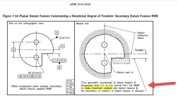
Figure7-34_kulble.jpg


How would I properly gage the part in the example below? Datum C does not have a position or profile tolerance to AB. Would I just make datum feature C parallel to the DRF or would I make the datum simulator at Nominal and rotate C around B until the high points touch the simulator?
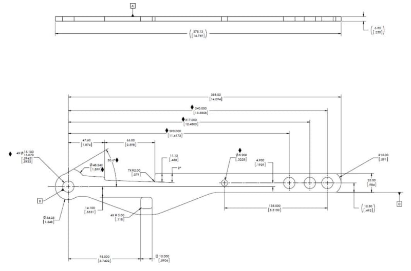
example-1_zjkupq.jpg
 
Replies continue below

Recommended for you

DGN1975,

There are no geometric controls or FCF to speak of on the drawing you provided, despite there being datum feature symbols. An FCF which references said datum features (ie: 0.3(M) position to A|B), as well as FCF's which provide a relationship between the referenced datum features (ie: 0.2 profile to A) would be necessary in order to answer your question.
 
Lets say this:
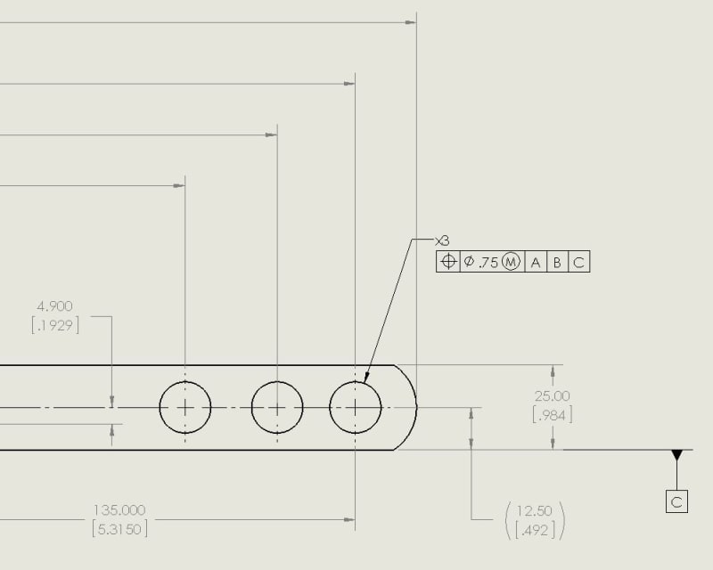
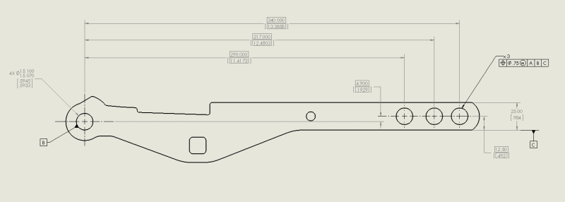
And assume the dimensions associated with those wholes to the datums are basic
FCF-1_g3uqcv.jpg
 
If nothing says where datum feature C is relative to datum features A and B, then the part definition is incomplete.
 
As a clocking datum, datum plane C provides an orientation reference to the 3rd plane of the datum reference frame, which needs to be exactly parallel to it and intersect at a right angle with the second plane at the axis of datum feature B. That alone doesn't provide a full orientation constraint to the part because depending on the exact offset of the datum feature simulator C from datum axis B *, the part and the pattern of 3 holes will end up oriented differently. For full definition a profile tolerance locating datum feature C relative to B is needed.

Edit: * the standard requires basic fixed location and orientation of all datum feature simulators in relation to each other, but this specific behavior that requires progression from MMB towards the feature for a datum feature referenced RMB and located at an offset to a higher precedence datum axis is one of the exceptions. In that type of cases I would say that the basic dimensions between datum features provide only an approximate location for the relevant datum feature simulator.
 
Thanks for all the responses.
I tried to clean up the print to clarify what i'm asking. Basically without a control/tolerance of C to datum B, sounds like datum simulator C would not stay at basic but just "translate" to touch as much of Datum Feature C as possible (parallel to eachother)
pic1_ddfgms.png
 
Since C is referenced RMB, the C simulator will not stay at basic even with profile controlling C with reference to B.
 
DGN1975,

Without controlling B to A and C to A|B none of the datum features have any requirement to be in any particular orientation/location to each other. Holding a feature relative to A|B|C is meaningless if the relationship between A, B, and C is not defined.

3DDave - I assume you meant INcomplete...?
 
chez311 said:
Holding a feature relative to A|B|C is meaningless if the relationship between A, B, and C is not defined.

DGN1975,
I generally agree with the above, but I hope you find it clear that controls applied to datum features control the datum features, not the datum feature simulators. I suppose that "the relationship between A, B, and C" mentioned above is the relationship between datum features, and I would say that this relationship is currently not controlled, in the sense that tolerances for mutual orientation/location are not defined. However, the basic relationship between datum feature simulators, and therefore also between the datums associated with those simulators, is defined by the basic dimensions and implied basic orientation. It is not dependent on tolerances. The only reservation in this specific case being that datum feature simulator C is required to progress from MMB at the direction of LMB (until maximum possible contact with the feature), and without a profile tolerance on datum feature C the location of this MMB boundary is ambiguous. If the datum features would be for example 3 perpendicular plane surfaces (meaning that they have no location requirements to each other), you wouldn't have this issue. Although in this case too, without tolerances controlling the perpendicularity of those datum features the drawing would be incomplete and you could get functionally inadequate datum features.
 
Status
Not open for further replies.

Part and Inventory Search

Sponsor