Continue to Site

Eng-Tips is the largest engineering community on the Internet

Intelligent Work Forums for Engineering Professionals

  • Congratulations MintJulep on being selected by the Eng-Tips community for having the most helpful posts in the forums last week. Way to Go!

Section Class 6

Status
Not open for further replies.

dik

Structural
Apr 13, 2001
25,843
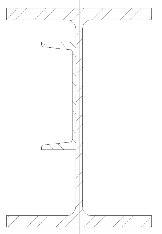
Can this composite section ever be considered as a Class 2 section?

Clipboard01_a2d0zv.jpg


I thought it had to be symmetric in the plane of the loading to be Class 2. The effect of adding a channel for composite capacity is very limited and the original section is Class 1 and you can use the plastic section Zx. The resulting is not Class 2, I think, and the effect of using the composite section modulus Sx results in a lower moment capacity than the unreinforced section.

Interesting puzzle? Any comments?

-----*****-----
So strange to see the singularity approaching while the entire planet is rapidly turning into a hellscape. -John Coates

-Dik
 
Replies continue below

Recommended for you

Wait, my yield order was backwards there. Here's an arguable design method. Set the flange of the channel furthest from the neutral axis to the yield stress, yield everything outside of that point and do an elastic distribution inside that point back to zero stress. Now you have your symmetrical wide flange yielded and your class three flanges not exceeding yield.

That potentially meets the code intent. It likely exceeds the plastic capacity of the wide flange but is definitely less than the plastic capacity of the combined section. Slightly less than three sum of the combined capacities if the class one wide flange and class three channel.
 
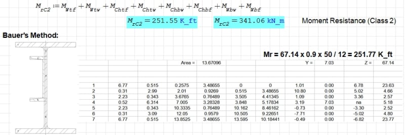
Just finished the SMath program... Calculated Mr is 249 K-ft... and using the summation of the Zx for both the C section and the W section is 254 K-ft... the C section at 44 Grade... about as close as dammit is to swearing... The moment resistance is about 250 K-ft... I never design closer than that anyway...

-----*****-----
So strange to see the singularity approaching while the entire planet is rapidly turning into a hellscape. -John Coates

-Dik
 
Dik
If the channel has a different yield strength don’t forget to transform it’s Zx to match the wide flanges Fy.

If your up for it my section properties tool on the toolbox will compute Z taking into account the different Fy’s. It numerically solves for a neutral axis depth by solving the static equation Tension-Compression=0 the “error” reported on the site is the resulting delta of tension-compression. The resulting Zx is then the internal moment couple divided by the Fy of the first shape to satisfy Mp=Zx*Fy assuming that shape 1’s Fy is the basis.(Link)
 
Yeah, class 1 is required to be symmetric in the plane of loading, but that is required to use plastic analysis and not to use the plastic section modulus. I think you could include the effects of asymmetry by either including some twist on the section or otherwise resolving the eccentricity of the plastic forces.

I still can't find any reference preventing the plastic capacity being used for bi axial bending, can anyone point me to that?
 
Thanks Celt... that's been done. With programs I usually include different steel types for different elements.

Clipboard01_lsypgp.jpg


-----*****-----
So strange to see the singularity approaching while the entire planet is rapidly turning into a hellscape. -John Coates

-Dik
 
Interesting check...

Clipboard01_fpyl6w.jpg


-----*****-----
So strange to see the singularity approaching while the entire planet is rapidly turning into a hellscape. -John Coates

-Dik
 
Response from the CISC... No comment on the Class; as noted, the increase is minimal.

Clipboard01_y9u25r.jpg


-----*****-----
So strange to see the singularity approaching while the entire planet is rapidly turning into a hellscape. -John Coates

-Dik
 
Dik:

Do you have a reference for Bauer's Method you are able to share?

In your spreadsheet it doesn't look like you have accounted for different yield strengths of the shapes. I'll update my site later today to include a shape template for channels not including the fillets based on the attach info, (I should be able to work out the interior fillet from the K dimension but for now the properties are close enough to the manual without it, AISC nor ASTM provides any info on the flange toe fillet anyone know if this info exists?)
Capture_x1vrkm.jpg


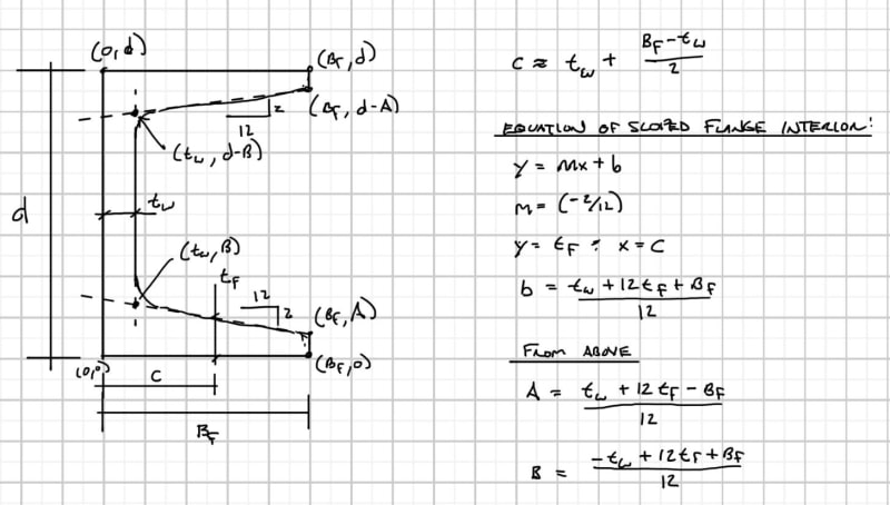
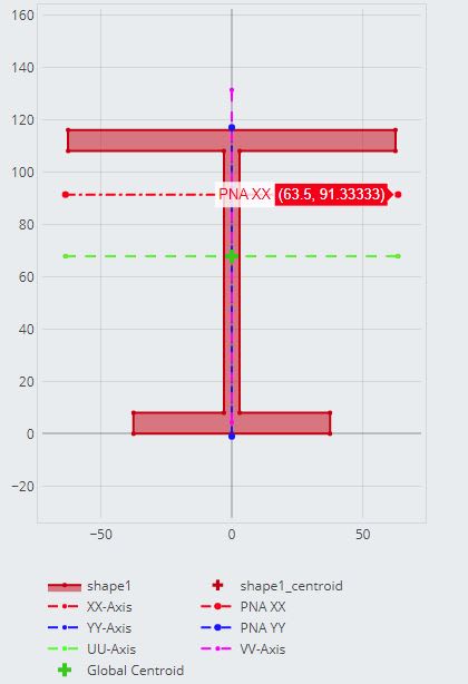
Here is what I assumed for the top of the channel inferred from your yn dimension of block 3 in your spreadsheet:
Capture2_k3dqju.jpg


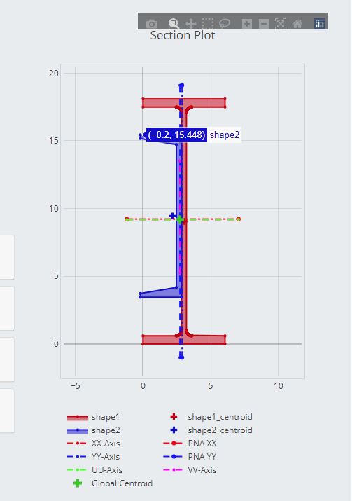
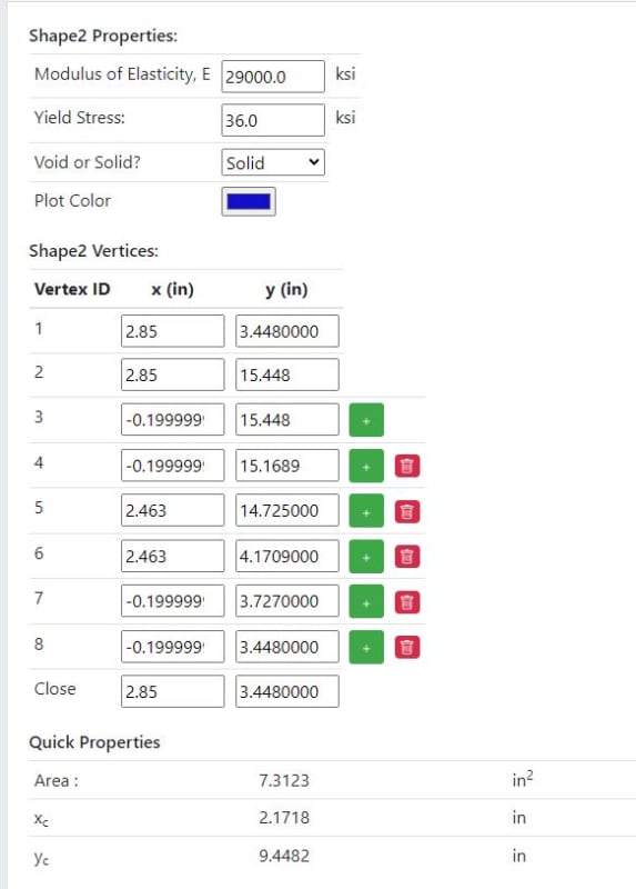
Coordinate information for the Channel (I have a template built for wide flanges that approximates the fillets as several straight sections):
Capture3_il7u9s.jpg


Resulting Properties (note that Z is based on 50 ksi Fy of the Wide Flange and accounts for the channel being 36 ksi):
Composite Section Results
Area 20.866 in2 Cross-Section Area
Transformed Area 20.866 in2 Transformed Cross-Section Area
Centroid (2.729,9.190) in Centroid in Global Coordinates

Properties about the Centroidal XX,YY Axis
Ixx 859.945 in4 Moment of Inertia (Second Moment of Area) about the XX-Axis, ∫ y2 dA
Iyy 30.537 in4 Moment of Inertia (Second Moment of Area) about the YY-Axis, ∫ x2 dA
Ixxyy -1.625 in4 Product of Inertia, ∫ x y dA
Izz or Jzz 890.482 in4 Polar Moment of Inertia, Ixx+Iyy
Sxx,top 96.510 in3 Elastic Section Modulus to the Top Most Vertex, Ixx / ymax
Sxx,bottom 93.579 in3 Elastic Section Modulus to the Bottom Most Vertex, Ixx / ymin
Syy,left 10.425 in3 Elastic Section Modulus to the Left Most Vertex, Iyy / xmin
Syy,right 10.425 in3 Elastic Section Modulus to the Right Most Vertex, Iyy / xmax
rxx 6.420 in3 Radius of Gyration about the XX-axis, √ Ixx/Atransformed
ryy 1.210 in3 Radius of Gyration about the YY-axis, √ Iyy/Atransformed
rzz 6.533 in3 Radius of Gyration about the ZZ-axis, √ Izz/Atransformed

Plastic Section Moduli, Fy=50.000 ksi
Zxx 112.063 in3 Plastic Section Modulus for Moments about the XX-Axis ( Error: 7.206e-09, Iterations: 34 )
Zyy 15.830 in3 Plastic Section Modulus for Moments about the YY-Axis ( Error: -9.789e-09, Iterations: 38 )
Zuu 112.063 in3 Plastic Section Modulus for Moments about the UU-Axis ( Error: -3.038e-10, Iterations: 34 )
Zvv 15.828 in3 Plastic Section Modulus for Moments about the VV-Axis ( Error: -7.119e-09, Iterations: 39 )

Principal Axis
Iuu 859.948 in4 Moment of Inertia (Second Moment of Area) about the UU-Axis
Ivv 30.534 in4 Moment of Inertia (Second Moment of Area) about the VV-Axis
Iuuvv 0.000 in4 Product of Inertia
θuu 0.112o Rotation from XX-Axis to the UU-Axis
θvv 90.112o Rotation from XX-Axis to the VV-Axis
 
I found the Bauer reference on this site... and downloaded the reference... The red notes are my comments... attached

[URL unfurl="true"]https://res.cloudinary.com/engineering-com/image/upload/v1695148074/tips/bauer_1997_plastic_modulus_aisc_00_o538en.pdf[/url]

As far as Bauer's approach... I don't account for the different yields strengths, but in my SMath program, I do... there's a really close correlation between the Bauer and the SMath for steels using the same yield and the SMath accommodates the real difference.

Who uses Grade 36 anymore, maybe for things like plate and BAR stock. The spreadsheet works on areas only and I guess I could try to modify them to acommodate for this using a modified area of some kind... I used the Bauer method just to 'confirm' the SMath output. I just noticed a 'hiccup' in my calcs. With SMath I use fy = 350 MPa and my spreadsheet I use fy = 50 ksi... It makes a bit of a difference. [upsidedown]

-----*****-----
So strange to see the singularity approaching while the entire planet is rapidly turning into a hellscape. -John Coates

-Dik
 
Thanks Dik

I get good agreement with the example in that document:
Capture_a0taw5.jpg

y,bar = 116 mm - 91.3333 mm = 24.66667 mm

Capture_bqf6js.jpg
 
Same here, but I didn't check their example... compared it to the SMath output... Thanks for the confirmation...

-----*****-----
So strange to see the singularity approaching while the entire planet is rapidly turning into a hellscape. -John Coates

-Dik
 
I don't want to say ppl are overthinking this.. but deep bridge girders can have longitudinal stiffeners in the web that would make the section in theory 'non symmetric'. There is no penalty in moment resistance for this longitudinal stiffener in my code.

We also have done hybrid girders which use higher strength flanges than the web material, as the web material carries a force that is generally lower than needed in the flange. Bridge girder webs are generally deep and thin, I dont think anyone in my industry would bat an eye if we bolted a channel on a web of a bridge girder.

If I were to see this in the field I would ignore the channel and evaluate the wide flange only.


Not overthinking... I rarely do that...

I was just coordinating my thoughts on the matter. The longitudinal stiffeners on bridge girders are for a totally different purpose. They are to provide stability to the web against shear buckling and have nothing to do with increasing the flexural capacity.

I was going to treat it as a Class 2, but it didn't strictly conform to a Class 2... likely a Class 3... I just wanted to see how other engineers would address this.

The use of the channel has two effects... The strengthening of the W section is minimal. In addition the EOR has called for a CJP weld of the C section to the W section. This is not only improper, but the limited clearance between the inside of the W beam flange and the C section flange makes it extremely difficult to weld...

It's not overthinking... it's a learning process... and a good one. [pipe]

-----*****-----
So strange to see the singularity approaching while the entire planet is rapidly turning into a hellscape. -John Coates

-Dik
 
Fair enough Dik. So you did end up evaluating this as a class 3?
 
I'm happy with Class 2... and have asked the EOR to confirm... I've also suggested reinforcing with round BAR material in the web-flange fillets on one side, too.

-----*****-----
So strange to see the singularity approaching while the entire planet is rapidly turning into a hellscape. -John Coates

-Dik
 
Just a caution... I was using my Bauer spreadsheet to calculate another section and got some 'odd' answers... I then checked the spreadsheet, by introducing another segment that would have no impact on the final shape. The added segment gave a slightly differnet answer... I'll check this out a little further.

-----*****-----
So strange to see the singularity approaching while the entire planet is rapidly turning into a hellscape. -John Coates

-Dik
 

Yesterday, the EOR gave approval for the alternative manner in providing the round BAR reinforcing in the fillets. Also intermittent weld as a reduced length. Reinforcing length is about 70% of the beam length and no CJP (?) welds required.

-----*****-----
So strange to see the singularity approaching while the entire planet is rapidly turning into a hellscape. -John Coates

-Dik
 
Status
Not open for further replies.

Part and Inventory Search

Sponsor