Continue to Site

Eng-Tips is the largest engineering community on the Internet

Intelligent Work Forums for Engineering Professionals

  • Congratulations GregLocock on being selected by the Eng-Tips community for having the most helpful posts in the forums last week. Way to Go!

Section Cut 1

Status
Not open for further replies.

Shz713

Structural
Aug 21, 2015
221
Hi all,

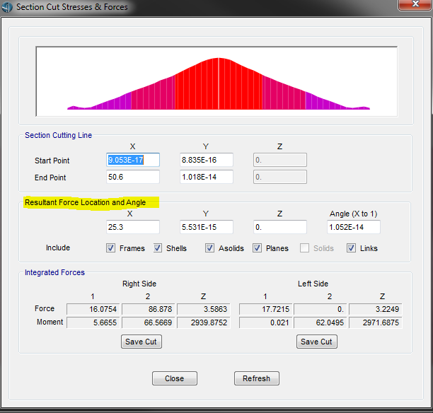
I have made a slab using shell elements. I would like to draw a section through longitudinal direction of slab to view the shear and moments by plotting them in Excel. When I use section cut definition in SAP2000, I tried defining both by group and quadrilateral plane but the output is just as one point. here is the link to what is described by CSI Knowledge Base: Link

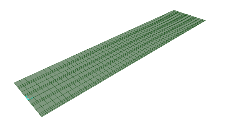
This is the slab I want to draw a section cut through its centerline. i already grouped all of these elements and tried defining different quadrilateral plane, but none of them worked.

Any suggestion is appreciated
slab_clw0x3.png


Shoot for the Moon, even if U miss, U still land among Stars!
 
Replies continue below

Recommended for you

The section cuts allow you to perform force integration on its entire length so you get one value (F1, F2, F3, M1, M2 and M3) for each section cut. To plot the shear and moment distribution you need to create several section cuts, all along and orthogonal to the longitudinal centre line.

This is a lot of work, creating all the quadrilaterals, so what I usually do is using the import/export to Excel features and generate all section cuts and quadrilaterals in Excel. I'm developing a VBA tool to help but it is still an ongoing side project.

Hope it helps.
 
Thanks heaps for your reply,

If I do different section lets with unit width, should I define quadrilateral plates using four node points coordinates? In that case, it will be almost 80 meter considering that slab length is 80m! Can you show with let's say 5 m slab how you define section cuts to plot moment and shear profile along bridge span?

So I take only M1 in Z direction as maximum positive moment and F1 as maximum shear? How about maximum negative moment?


Cheers

Shoot for the Moon, even if U miss, U still land among Stars!
 
I defined different quadrilateral planes but I only obtained results at one point.
For instance for a 5 m length and 1.5 m width, assuming it is meshed by maximum size of 0.5, If I want to plot along center-line moment and shear profile, how do I do that? I cannot figure it out

Thanks again

Shoot for the Moon, even if U miss, U still land among Stars!
 
I finished the VBA tool for the generation of xlsx files with the section cuts definition for their import into SAP2000, which I enclose in this post. This is for slabs in the xy plane and for version 17.2.0 of SAP2000.
Try to study the SAP2000 manual and this spreadsheet and you'll probably get a good insight on what you have to do.
 
 http://files.engineering.com/getfile.aspx?folder=aa86b22e-375a-4a44-89d2-5caa0a6575ba&file=Section-cuts_SAP2000_v1.0.xlsm
Thanks a lot for the VBA tool, it works seamlessly! I just have a few questions and I appreciate if you could answer them:

1-what is division for?
2-cut direction does it make any difference? I mean it supposed to cut from initial to end point regardless of direction
3-Is it okay to define vertical plane, viz. keeping x=0 and use only Z and Y?

Lastly, which one of the output represents moment (M1,M2,M3) and which one represents shear (F1,F2,F3) {in frame elements we take M33 and V22 often} assuming the default axis for shell (local axes 1 parallel to global X, local axes 2 parallely to global Y, local axes 3 parallel to global Z). I reffered to here Link but still little bit cofnused.

Peace [thumbsup2]

Shoot for the Moon, even if U miss, U still land among Stars!
 
Forgot to ask, what is Alpha for? Is it angle between X and Y axes?

Shoot for the Moon, even if U miss, U still land among Stars!
 
I'm glad it works. Answering your questions:
1 - Divisions establish the number of section cuts in a segment. Segments are defined between main points (column locations). Play with the values and look at the plan view.
2 - SAP2000 allows to perform the integration from either side, positive or negative. The results shouldn't be too different.
3 - Not with this tool, at least directly. You can try working on the xy plane and changing the coordinates manually on the import files
4 - Output conventions in SAP2000: you'll have to interpret it using the manual and the help file and comparing it to your hand solution.
5 - Alpha is the angle of each segment with the x axis.

Hope it helps.
 
Your answers are crystal clear. I guess when a transverse section cut is defined, alpha would be 270 measuring counterclockwise from global X axes to the positive X axis of the local coordinate system in which the integrated forces are reported.
I tried to check accuracy of spreadsheet comparing with drawing section cut in SAP2000, I noticed that it integrates forces at one location when section cut is drawn in graphical user-interface. I checked the values reported by values at same location by spreadsheet, but they're not same at all. Did you try validate its output? i checked for very small xy plane and the results did not match.

1_c0ug24.png


Shoot for the Moon, even if U miss, U still land among Stars!
 
The spreadsheet is working. It was checked against other software and to the Equivalent Frame Method for flat slabs.
 
Indeed it is working, I meant to crosscheck with SAP2000 results.
2moro I give it more detailed look to see the differences.

Cheers,

Shoot for the Moon, even if U miss, U still land among Stars!
 
To compare with SAP section cut results, section cuts must be drawn transversely not longitudinally, also group cut must be set to ALL--> doing so, Excel and section cut results match!

I would like to know:


1-quadrilateral dimension above and below slab(az), I noticed that it changes output to some extent. Is 0.1m reasonable?

2-for left and right width, it is better to include the whole width in which we're interested to get the force output. I realized that if left and right width are not the complete width (e.g. in my case left and right width are measured to outermost left and right side if I need the force profile within the middle), the result is not correct. So It is better to include the exact width.

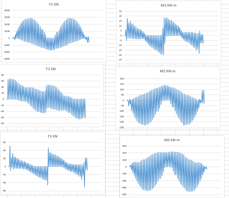
3-for analysis purpose, which force output you take? I reckon for shear must be F3, but for moment I am not too sure because I am getting similar shapes! Below graphs are force profile for slab which I shown in the beginning of this thread. Axes are default as well.

Thanks a lot [glasses]

Capture_tgg7me.png


Shoot for the Moon, even if U miss, U still land among Stars!
 
Forgot to mention, I can't figure out how to plot force profile for vertical shell elements. For instance in case of having a shell element vertical shown below, how I can plot force profile (regardless of Excelsheet). Should I plot forces at centerline, or get top and bottom and then take average?

Capture_bvfj6g.png


Thanks

Shoot for the Moon, even if U miss, U still land among Stars!
 
I'm glad the tool is useful and that you've figured out how to use it, doing sections orthogonally to the longitudinal axis.

Regarding your questions:
1 - I've never checked the influence of the quad extra dimensions and that certainly needs attention. Good point.
2 - You're right. I think that that has to do with the way that SAP2000 integrates the forces using the nodal values. I had noticed it doing manual section cuts.
3 - The sign convention is indeed confusing. What I usually do (as with any other design that involves FEM...) is do a equilibrium hand calc first to get a feel of the target values. Then I use the moment and shear distribution that most resemble the hand calculated values.
4 - Never checked it, but there are probably two options: a) use left and right widths of 0.1, mid-height main points and a z value of half the height; b) generate section cuts as if the elements were on the xy plane and swap manually the coordinates in the import files. This will be included in other spreadsheets I'm developing: automatic generation of section cuts for beams modelled with shells in a vertical plane and for shear walls (linear walls and shafts) in a vertical plane.

Hope it helps.
 
Thanks for your prompt response.

With regard to point 3, I agree with that in case I am doing slab design, shear wall design (something I can figure out imposed loading to do manual calculation). The shown figure is part of bridge deck, namely is diaphragm at abutment. In such case, it is very hard to do ,annual calculation when you want to estimate the load effect due to truck load! So I have no way other than section cut as of now. It is very pity that shell elements have such complication, I've been thinking to make whole my simulation using frame elements as it is way more easier to get load effects.

For point 4, I did that before; though the issue is that SAP2K automatically report forces @ joints. In the shown figure above, I have only points at top and bottom surface. In that case, if I define mid-height points as main points for section cut, then I am getting zero forces. I kept X coordinates as zero, then I incremented Y coordinates based on points, for Z coordinates I used the actual location of points intersecting with Z axes. I don't want to be rude but I hope you make that spreadsheet very soon because I really need to get forces for vertical shell elements and I am clueless as of now [pc]

Shoot for the Moon, even if U miss, U still land among Stars!
 
Well, you could try to increase the number of elements and give +Z and -Z coordinates a bit larger than those of your model. Regarding the new spreadsheets, they aren't coming out any time soon...
 
Would you elaborate what you mean by increase in number of elements? Whatever trick I knew I tried but all the reported forces are zero at selected locations

Shoot for the Moon, even if U miss, U still land among Stars!
 
Well, the spreadsheet is working for a beam defined with shell elements in the XZ plane. I've tested option a) (use left and right widths of 0.1, mid-height main points and a z value of half the height) for a two spans beam and it's working. I enclose a link for the sap2000 model and all relevant spreadsheets.

Link

The beam is a 16m long beam with two spans, 0.25x1.00m2 section, loaded with self-weight and a uniform live load of 100kN/m. ULS is defined as 1.35DL+1.5LL.

Hope it helps.
 
I realized that I was defining my Z coordinates, out of plane, so the results were zero forces. When the mid-points are chosen, the the upper and lower portions of defined plane lies within shell.
By the way, do you specify offset as 0.1 avoiding zero force/instability or it just as an option for user to include specific portion of element?

Shoot for the Moon, even if U miss, U still land among Stars!
 
It is just a random value I chose, sufficiently small to minimize intersection with any other elements and sufficiently large to create a quadrilateral without numerical problems.
 
Status
Not open for further replies.

Part and Inventory Search

Sponsor