Shz713
Structural
- Aug 21, 2015
- 221
Hi all,
I have made a slab using shell elements. I would like to draw a section through longitudinal direction of slab to view the shear and moments by plotting them in Excel. When I use section cut definition in SAP2000, I tried defining both by group and quadrilateral plane but the output is just as one point. here is the link to what is described by CSI Knowledge Base: Link
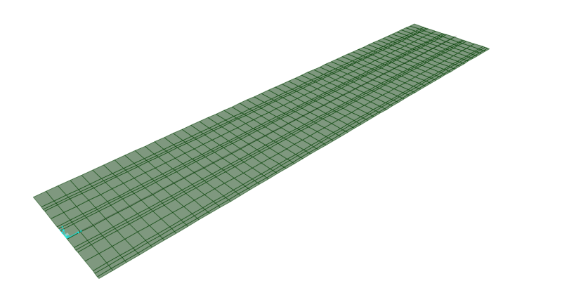
This is the slab I want to draw a section cut through its centerline. i already grouped all of these elements and tried defining different quadrilateral plane, but none of them worked.
Any suggestion is appreciated

Shoot for the Moon, even if U miss, U still land among Stars!
I have made a slab using shell elements. I would like to draw a section through longitudinal direction of slab to view the shear and moments by plotting them in Excel. When I use section cut definition in SAP2000, I tried defining both by group and quadrilateral plane but the output is just as one point. here is the link to what is described by CSI Knowledge Base: Link
This is the slab I want to draw a section cut through its centerline. i already grouped all of these elements and tried defining different quadrilateral plane, but none of them worked.
Any suggestion is appreciated

Shoot for the Moon, even if U miss, U still land among Stars!


