Continue to Site

Eng-Tips is the largest engineering community on the Internet

Intelligent Work Forums for Engineering Professionals

  • Congratulations The Obturator on being selected by the Eng-Tips community for having the most helpful posts in the forums last week. Way to Go!

Section reinforcement using bolts 1

hamza41

Civil/Environmental
Jul 7, 2015
57
Hi Everyone,

We are reinforcing a corroded existing W16x36 with two centred C12x30 channels.

I would like your opinion on how to determine the efforts on the connection bolts and their spacing as the shear flow is null. I detemined the maximum force from the stress on the half top of the channels, and I'm not sure on many longitudinal bolt I should divide it.

And do we have to provide a clamp load from the bolts, how to calculate it in this case ? do the bolts need to be pretentioned ?
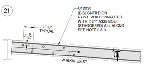
1737740291171.png
Thank you for your help.
 
Replies continue below

Recommended for you

I think that the bolts can be snug tight.

I would provide enough bolts such that 100% of the loads applied to the W16x36 can be sent out laterally to the two channels. It won't take much because, as you mentioned, there is a negligible shear flow demand. Some kind of judgment based, reasonable minimum spacing may well govern.

Where you may have a more significant bolting demand is at the ends of the channels. If the channels don't have independent bearing support, then you'll need a concentrated pattern of bolts to move the shear in the channels back into the W16x36. and down to the beam support, whatever that is.

Are your channels going to be interrupted by existing members that are supported by the W16 and frame into it? If so, that may factor in.
 
Thank you for your reply, I really appreciate.
But how can we be sure the loads are fully transmitted to the channels and the bolts are resisting ? Is there a way to calculate the efforts on the bolts using the pressure on the channels from the bending moment ? and how to distribute it on the bolts ?

The client is asking how the loads can be transfered to the channels when the holes are 1/16" larger than the bolts.

It's a good point you mentioned about the shear move from the channels back to the W16, I've missed that. But do you think we still need it if the W16 resists already all the shear load alone ?

Thank you again.
 
Thank you for your reply, I really appreciate.

You're most welcome.

Is there a way to calculate the efforts on the bolts using the pressure on the channels from the bending moment ?

This is much easier than you're imagining. You don't need the moments or even the shears (except at the ends as I mentioned perhaps). Assuming that you are effectively abandoning the existing beam, you'll just assume that 50% of the loads applied to that beam need to get transferred over to the channel laterally, right near where the loads are applied. And you'll use bolt shear to do this.

Ever designed the fastening pattern on a multi ply wood beam? Similar concept.

The client is asking how the loads can be transfered to the channels when the holes are 1/16" larger than the bolts.

How is this any different than any other bolted connection where the holes are always 1/16" larger than the bolts? Either you will accept that extra 1/16" deflection to take up the slop in the bolt holes or you will need to make the bolts slip critical to prevent that (expensive, particularly the testing requirement).

But do you think we still need it if the W16 resists already all the shear load alone ?

Yes. It's not about which member can resist the shear. It's about being consistent with your load path. If you've used the channels to resist flexure, then they also need to resist the shear that would complement that flexure. And, once that shear is in the channels, it needs to go some place. Either to an independent support or back into the existing beam web.
 
Thank you again,

This is much easier than you're imagining. You don't need the moments or even the shears (except at the ends as I mentioned perhaps). Assuming that you are effectively abandoning the existing beam, you'll just assume that 50% of the loads applied to that beam need to get transferred over to the channel laterally, right near where the loads are applied. And you'll use bolt shear to do this.

Ever designed the fastening pattern on a multi ply wood beam? Similar concept.

If I understood your idea, you mean if for example we are adding a 50 KN concentrated load on the beam, we consider 25 KN as a shear load on the bolt, and if it is a 10KN/m we condier 10x0.3=3KN on the bolt ?
I have no experience in wood design.

How is this any different than any other bolted connection where the holes are always 1/16" larger than the bolts? Either you will accept that extra 1/16" deflection to take up the slop in the bolt holes or you will need to make the bolts slip critical to prevent that (expensive, particularly the testing requirement).

That's what I think too, there would be a small slip before the bolts take the effort by shear resistance. He even asked me to verify the beam rotation to be sure the displacement exceeds the 1/16".

Yes. It's not about which member can resist the shear. It's about being consistent with your load path. If you've used the channels to resist flexure, then they also need to resist the shear that would complement that flexure. And, once that shear is in the channels, it needs to go some place. Either to an independent support or back into the existing beam web.

In our case, we are reinforcing this beam to support a monorail. I guess we only have to consider shear coming from this new added load wich is around 26 KN. The shear is then 13 KN which can be resisted by a single bolt. Am I right, or did I miss something ?

Thank you a lot for your help.
 
Is your load path: force applied to W16 -> transferred to C12s with bolts -> back to W16 for end shear connection?

If so, is the beam only corroded in the middle?

At the end of any built up member like this where I need to transfer shear back into main member, I always specify 4 bolts minimum if I can fit it, even if the loading doesn't require it. Something about a nice 2x2 bolt group gives me confidence.
 
Thank you for your reply.

Is your load path: force applied to W16 -> transferred to C12s with bolts -> back to W16 for end shear connection?
Yes.

If so, is the beam only corroded in the middle?
Not only in the middle. We are reinforcing it because we are using it to support a new monorail load.

At the end of any built up member like this where I need to transfer shear back into main member, I always specify 4 bolts minimum if I can fit it, even if the loading doesn't require it. Something about a nice 2x2 bolt group gives me confidence.
Can we use a fillet weld at the end intead ? Is there another reason to provide more bolts if one is enough for the load transfer ?

Thank you again !
 
Thank you for your reply.


Yes.


Not only in the middle. We are reinforcing it because we are using it to support a new monorail load.


Can we use a fillet weld at the end intead ? Is there another reason to provide more bolts if one is enough for the load transfer ?

Thank you again !
I love welds for reinforcement of steel members unless it's difficult or not allowed on-site.

Also if there is damage on the end of the member you can't rely on the force going back into the existing member. Your reinforcement would have to bypass that load path completely.

At the end you should always use a minimum of 2 bolts even if just 1 suffices. You want that tiny bit of fixity. In general I like 4 minimum because the cost difference is negligible and it just looks better.
 

Part and Inventory Search

Sponsor