Continue to Site

Eng-Tips is the largest engineering community on the Internet

Intelligent Work Forums for Engineering Professionals

  • Congratulations KootK on being selected by the Eng-Tips community for having the most helpful posts in the forums last week. Way to Go!

Sectioning a rib in a derived part.

Status
Not open for further replies.

moon161

Mechanical
Dec 15, 2007
1,181
I'm working with castings, so I have a drawing made of the casting, and then a drawing of various machined parts from the same casting. WIth the castign dwg, when I section the casting, I can exclude the ribs of the casting from the section.

The machined parts are a derived part, so the first feature of the derived part is just the body of the casting. Is there any way to exclude the ribs from the section when I make a drawing of this part? It's not obvious, and I want to get away from using sketched lines and hatch boundaries in the view because that sucks.
 
Replies continue below

Recommended for you

When I do weldments, I model them in two (or more) configurations, as welded and as machined. Then I assign a certain configuration to each drawing view. That way I can create configurations as needed for each view. Could you do it that way, configurations instead of derived parts? Not sure that would solve your problem but I think it might. You could create a configuration with ribs suppressed, and use it for the related views.
 
So default configuration could be AS CAST and then different machinings could be derived configurations of it. This would progagate minor changes if they were ever made to the castings children just like a derived part would.

Getting away from 1 for 1 correspondence between drawings and parts is taboo in SWX world though. I should see what our CAD standard says.

Another idea that i've suggested is just modelling the parts in SWX as required, checking them and then leaving the drawing in legacy 2D until revision time.
 
moon161 said:
Getting away from 1 for 1 correspondence between drawings and parts is taboo in SWX world though.

Nothing I can think of in SolidWorks that makes this the case... Totally up to your standards and practice within your company. Maybe PDM affects? I've not used PDM. I'm pretty sure I'd have no issues doing multiple drawings of various configs of a single part.

 
Not sure what you mean exactly by "Getting away from 1 for 1 correspondence between drawings and parts". The drawing of your derived part refers to the casting as the "raw material" or source part, doesn't it?

Usually I label my weldment drawing views as "As Welded" or "As Machined". In fact, you can link a view label to the configuration name property of the part shown in the view. That view name or config name could include the phrase "Ribs Omitted for Clarity".
 
We have completely different part numbers for the castings and finished parts. In my experience, if the part number is 123456 then anything besides 123456.sldprt and 123456.slddrw is looking for trouble. If my casting is 123456.sldprt and it has many children, which are configurations of the casting and then many drawings which point to it, doable and manageable things in my circumstance are not the same.
 
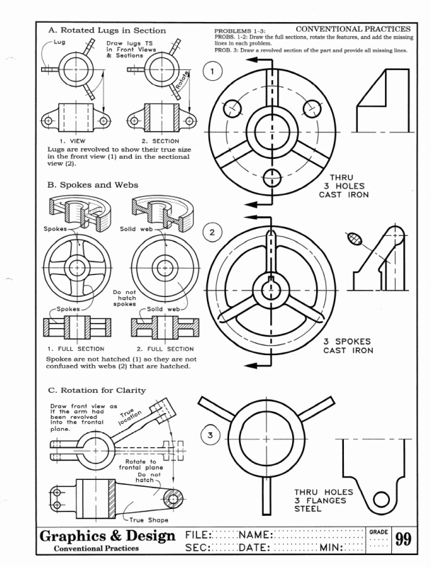
Actually I'm looking to do the opposite of ommiting ribs for clarity. We have probably hundreds of legacy drawings with ribs done to the preferred convention shown in the pic:
Foreshortened_Features_1_dt7yw5.gif


The rib is shown in the section but not hatched, and rotated to show fully in the section view instead of foreshortened. Previously, I've hidden lines and sketched new lines and hatch boundaries in but this sort of hybrid drafting sucks and results in a drawing that you can't point at the next part in the series and have the drawing done except for changing some notes and numbers. Except for the lack of a 3D product, a 2d drawing of a column with a break in it is great, because you just add what you need to the overall length dimension and save as the next drawing in the series.
 
Similar. I think I did the assignment shown decades ago
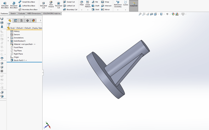
The best result would be to be able to do this with a derived part, ie. the casting body is the first feature of the machined part.
phpzEZZaB_jwxlfe.png


And why are the ribs not filleted if the part is cast iron, as noted?
 
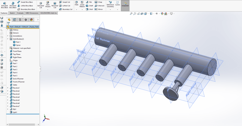
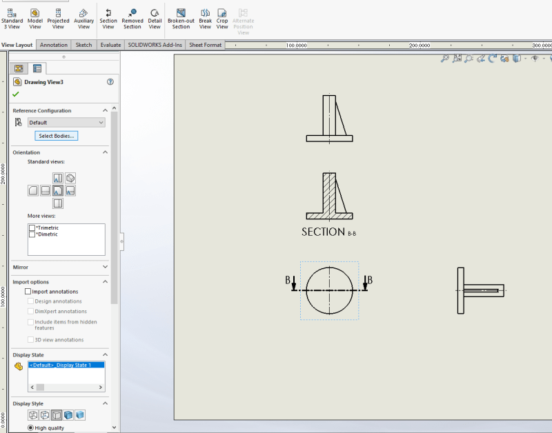
So you start with a part file for the casting and then use the split feature to seperate that part file into multiple bodies, which you then save out as distinct part files, correct? In these part files you have one feature in the feature tree; your "stock" feature, which makes your part a derived part and maintains the link, correct? Therefore, when creating a section view in the drawing for this derived part, there is no rib feature to select to exclude from your section view?
image_rdqtrr.png


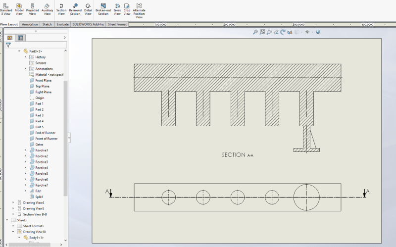
Assuming I have got that right, what I would do instead is use the split feature as before, but dont bother saving out the result as distinct part files. Instead do everything from the (now multi-body) master part. When creating a view in your drawing file you can select the bodies that you want to be included in the view, so you can use this to create drawings of the individual "parts". This method keeps the feature tree in-tact in the drawing file, allowing you to select the rib feature to exlude from a section view. It also just seems more robust to me, as you only have one part file and one drawing file to manage (you could have multiple drawing files but I would question the need).

Hope I have interpreted your question correctly and that this is helpful,

Cheers.

image_d8jxwv.png

image_x0posb.png

image_fypmfo.png


GSTP

Graduate Mechanical Design Engineer
UK
 
Status
Not open for further replies.

Part and Inventory Search

Sponsor