Continue to Site

Eng-Tips is the largest engineering community on the Internet

Intelligent Work Forums for Engineering Professionals

  • Congratulations KootK on being selected by the Eng-Tips community for having the most helpful posts in the forums last week. Way to Go!

Sectioning

Status
Not open for further replies.

SBaugh

Mechanical
Mar 6, 2001
6,685
I have been around for a while so I like my drawings to be up to ANSI standard, but I am a little confused about how the software is creating this section view.

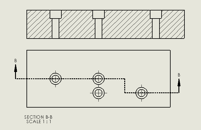
I don't think that this is a proper section line, but the software allows it to occur. So I am looking for some technical advice as to if this is properly represented and is acceptable within ANSI Std?

Its obvious you cannot dim to the block for proper information.
Sectioning_Example_t0i32d.jpg


Scott Baugh, CSWP [pc2]
CAD Systems Manager
Evapar

"If it's not broke, Don't fix it!"
faq731-376
 
Replies continue below

Recommended for you

I have never seen section lines like that. I'm not sure the standards cover exactly how the lines are drawn. But, in my experience, they need to be as simple and straight forward as possible.

ctopher, CSWP
SolidWorks '17
ctophers home
SolidWorks Legion
 
I agree ctopher, but SW allows this section line to be used which is concerning to me. I have found a few other section issues recently. To test out my previous finding I made this file and found this and I just don't think it's right or any proper Std.

Scott Baugh, CSWP [pc2]
CAD Systems Manager
Evapar

"If it's not broke, Don't fix it!"
faq731-376
 
SolidWorks is sort of known for giving in to customers, even when the customer is wrong. Someone demanded that this work this way; I guess the path length is correct, but that's one ugly outcome.
 
I agree with 3DDave. To save customers, if it's not 100% clear in the specs, they sort of give in to what customers want.
I personally will never do a section like that. It's not how I was trained.

ctopher, CSWP
SolidWorks '17
ctophers home
SolidWorks Legion
 
Oher than giving a better cross section of the 5th hole, How do they ever come up with increasing the length of the part because of the section line length. The section view length is so misleading!
The section line itself is allowed to change directions, but then you would get the 4th and 5th holes almost on top of each other.
"Just Say NO!"


"Wildfires are dangerous, hard to control, and economically catastrophic."

Ben Loosli
 
I've seen some "unfolded" section views where the section view was longer than the projection view but nothing like that! I've never seen a section line double back on itself. "Just say NO!" indeed.

----------------------------------------

The Help for this program was created in Windows Help format, which depends on a feature that isn't included in this version of Windows.
 
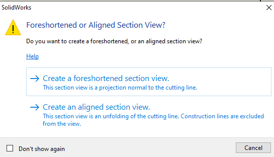
When creating a non-continuous section line in solidworks it comes up with the following message. The longer length is due to what they are apparently calling an "aligned" section view which as the message shows simply unfolds and follows the length of the section line - this is possible with this option even when the line doesn't fully reverse as in the image below.

It seems the default for non-continuous sections with only two segments is aligned, as well as any non-continuous section with segments at an angle other than 90 or 180 deg to each other. Some truly bizarre results are possible, even with the foreshortened view as it seems to choose the normal direction based on the segments at the end of the chain.

Interestingly this "aligned" view is now called "standard" in newer versions of solidworks. I'm not sure how they reasoned this should be considered "standard".


foreshorten_aligned_tbcmao.png


forehorten_aligned_2_ieev7j.png
 
I am not saying I would section a part like this, by any means, but when software allows a person to do this it's concerning. Stretching out that section, as it does, is wrong IMHO.

Scott Baugh, CSWP [pc2]
CAD Systems Manager
Evapar

"If it's not broke, Don't fix it!"
faq731-376
 
From paragraph 8.7.1 of ASME Y14.3-2012: "In order to include features not located in a straight line, the cutting plane may be stepped or offset (generally at right angles) to pass through those features....[These] offset section views are drawn as if the offsets were in one plane..."

That wording doesn't forbid what the OP is showing. But it is indeed strange to see.

John-Paul Belanger
Certified Sr. GD&T Professional
Geometric Learning Systems
 
I am not saying I would section a part like this, by any means, but when software allows a person to do this it's concerning. Stretching out that section, as it does, is wrong IMHO.

The functionality that allows you to incorrectly create an offset section view is the same functionality that allows you to correctly create an aligned section view. I think it's unreasonable to expect the software to prevent the misuse you illustrated. Drawings are intended to be understood by humans, and correctness depends on context. That assessment will require human judgment.

You may find this SOLIDWORKS Help page useful.

ASME Y14.3 is the relevant drafting standard.


pylfrm
 
I have seen aligned sections used in assembly views for gear trains.

Peter Stockhausen
Designer / Checker
 
What does the full length, switch backed, "pocket hose" section view accomplish ?

If all the holes are created the same ( c'bore Ø and depth, thru hole Ø ), I think a partial section showing just one fully dimensioned hole would be fine.
Then dimension the hoes/ positions in the plan view.
 
Status
Not open for further replies.

Part and Inventory Search

Sponsor