Continue to Site

Eng-Tips is the largest engineering community on the Internet

Intelligent Work Forums for Engineering Professionals

  • Congratulations KootK on being selected by the Eng-Tips community for having the most helpful posts in the forums last week. Way to Go!

(Seems like) rotor/load interia mistmatch on sustainably operated machine

Status
Not open for further replies.

alphawell

Mechanical
Feb 24, 2016
14
Hi there. Thanks for your attention.
I'm mechanical design engineer (maybe that's the root of the problem - I'm not that familiar with electrical realm of the question) and I fall short to find any plausible answer to the problem, described below, that perplexes me.
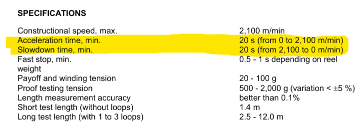
Since I'm working on a design of optical fiber rewinding machine (basically, the machine used to rewind the fiber from one reel to the other, maintaining the stable tension and winding pitch), I've made some kind of review of commercially available analogs. In one of the machines, that I’ve managed to become acquainted with, the reel is driven by direct drive (i.e. torque is transmitted in sequence servomotor -> disk coupling -> reel). The largest reel, compatible with this machine, as per datasheet, is 25 kg and 550 mm OD. Rated acceleration/deceleration time is 20 s (from angular speed 0 up to 127 s^-1), which makes the choice of the rated torque of the drive – 9,8 N-m – perfectly reasonable. But the thing the puzzles me so much is how is this drive supposed to cope with inertia of the load? The mass moment of inertia of the aforementioned reel is about 0,95 kg-m^2. Rotor inertia for this motor as per manufacturer datasheet is 0,0007 kg-m^2 and permissible load inertia factor is 5, i.e. maximum permissible load inertia is 0,0035 kg-m^2 – it’s incomparable with that of the reel.
Meanwhile this machine is considered as extremely reliable and well-designed by the end-user, and particularly there was no claims (never mind failures) on the reel drive system (I’m not sure that it’s appropriate to mention model and manufacturer name as it could be deemed as advertising).
For me (as a designer of the similar machine) this is a really important issue since I’m currently not sure depending on which characteristic should I base the motor sizing routing (because before I familiarized myself with this analog machine, I thought I’ll use 1:50 ratio planetary gearbox to reduce inertia in my design).
Could someone share at least a tiny cue for me to solve this issue?
Thanks in advance.


NX 10.0.3.5
 
Replies continue below

Recommended for you

It is unclear what your question is. What is "motor size routing"?
All rewinding processes are very similar. You need to control speed and tension of the let-off and the wind-up. It is usually desirable to control let-off and wind-up tension separately, particularly if the spool sizes can vary considerably. Driven nip rollers or capstans are used to control speed and to isolate the let-off tension from the wind-up tension. Motor torque control does not work well for controlling tension if there is any gearbox involved. Dancer arms are often the most robust and reliable way to control tension. Load cells can be used, but I look at load cells as dancer arms with only about 0.01" range of travel, so motor control must be very responsive to work, compared to true dancer arms.
 
1) The control of a winding (or rewinding) process is generally "closed loop", which means there is a recognizable feedback signal that helps adjust the motor's operation. Closed loop systems can typically handle larger differences between motor and load inertia (i.e., the "permissible load".
2) Not all servo motors are created equal - given the speed of operation for your direct drive system, chances are quite high that the servomotor has an integral gear. Typical gear ratios are in the 15-1 range for this power range.
3) Going to stick my neck out here: I believe the OP meant "motor RATING" when they stated "motor sizing routing".
4) Why can a servomotor get away with an integral gear and an external gear is frowned upon? Because of the complexity of the gear itself and the typical machining and assembly tolerances. An external gear will usually have sufficient clearance between teeth that a "backlash" effect is possible, which makes positional and torque control much harder than it has to be.

Converting energy to motion for more than half a century
 
Compositepro said:
It is unclear what your question is. What is "motor size routing"?
Gr8blu said:
I believe the OP meant "motor RATING" when they stated "motor sizing routing".
I sincerely apologize for confusing you, looks like during the final check word processor slightly distorted the original text. I mean "motor sizing routine" i.e. the procedure used to determine suitable motor specs. I'll try to further clarify my question as briefly as it possible. There are manufacturer's recommendations for particular types of motors generally (and servomotors specifically) which limit permissible rotor inertia / load inertia ratio. In the application, which I described in previous post, this ratio is clearly not maintained by designer (I’m absolutely sure because I have disassembled the machine, I saw the nameplate of the servomotor, the assembly drawings of the machine and the datasheet for this servomotor). As far as I understand, if the mass moment of inertia of the load is significantly greater than that of the rotor, the load is prone to “drive” the motor when it is supposed to decelerate, and operating of this system could be unstable. Now the question is: this machine performance is proven by the long-term operation, so how do these facts stack up?
Gr8blu said:
Closed loop systems can typically handle larger differences between motor and load inertia (i.e., the "permissible load".
And this is the part of the answer, thank you, Gr8blu. Yes, I guessed that limitation may differ for closed-loop systems. But how do I consider this difference in calculations? E.g. I know how much torque required drive should exert, since I know the mass moment of inertia and the angular acceleration, but how to assess the acceptable rotor/load inertia ratio for closed loop system?
Gr8blu said:
2) Not all servo motors are created equal - given the speed of operation for your direct drive system, chances are quite high that the servomotor has an integral gear.
Only in case if this is some kind of undocumented internal gear. I saw the servomotor personally and read the assembly drawing, it’s SGMSH-30DCA6F-OY Yaskawa/Omron servomotor. No gears are specified in datasheet.
Gr8blu said:
An external gear will usually have sufficient clearance between teeth that a "backlash" effect is possible, which makes positional and torque control much harder than it has to be.
Do I have to address the backlash if rewinding is run in one direction? Actually, I’ve inspected the second proof test/rewinding machine (of different brand other than first one) and its reel drive includes the toothed belt/pulley gear with ratio approximately 1:3 and Yaskawa Sigma V servomotor.
Anyway, thank you guys.


GetRobot.pro

 
I'd be curious to see the full specification with that inertia limit. Did it also specify an acceleration time?

There are 2 torques required for a spinning load.

The steady state torque or torque required to keep the load spinning at a constant speed. This torque is different for every speed. It is generally higher the faster the load is spinning.

The accelerating or decelerating torque, which is the torque required to accelerate or decelerate a load. The accelerating torque available is the torque the motor can produce minus the steady state torque (at the current speed). The more accelerating torque the motor produces, the faster the load can be accelerated. The more load inertia, the slower the motor can accelerate it.

I would have to believe the winder is spec'd to have a 20s acceleration time because of the available accelerating torque to accelerate the reel to speed.

 
LionelHutz said:
I'd be curious to see the full specification with that inertia limit. Did it also specify an acceleration time?
Which of them would you like to see? The load inertia limit is normally specified in datasheet for the motor, like this one:
Screenshot_2023-06-28_101454_twn6mg.png

And the acceleration time is specified in technical data list for the rewinding machine:
Screenshot_2023-06-28_101613_htgvx7.png

LionelHutz said:
The steady state torque or torque required to keep the load spinning at a constant speed. This torque is different for every speed. It is generally higher the faster the load is spinning.
Well this lies in slight contradiction with what I know about dynamics of spinning body. As far as I know (please correct me if I’m wrong), one does not need any torque to spin slick body in a frictionless bearing after this body had been accelerated (by means of the torque you mentioned as “accelerating”). So, power is consumed (and torque is exerted) In steady state only to compensate for the friction moment in bearings (cause our bearings are not frictionless). And I mentioned slick body because if one have to spin fan or agitator wheel (i.e. non slick body) one should account for the air/fluid resistance (and exert corresponding extra torque). The point is friction moment in rolling bearings insignificantly changes with the speed of rotation – primarily it depends on the coefficient of friction and normal force (in our example on the weight of reel, shafts etc).

Anyway, these speculations are not completely relevant to aforementioned case, since, strictly speaking, there is no steady state for this type of machine. Since fiber is normally wound irregularly, pay-off reel continuously accelerates and decelerates to compensate for slack or overtightened regions. The question is how to choose appropriate inertia of the motor to avoid possible complications when controlling the reel rotation.


GetRobot.pro
 
See the rated angular acceleration in the specification? You can't get that acceleration rate unless the load is within the rated load inertia.

You need to stick to the practical side of practical spinning loads, not wishful theories only pursued by energy storage companies. This is a winder, every steady speed will require a torque input just to keep it moving.
 
Status
Not open for further replies.

Part and Inventory Search

Sponsor