Eng-Tips is the largest engineering community on the Internet

Intelligent Work Forums for Engineering Professionals

Seismic Overstrength design

Status
Not open for further replies.

kurichan

Civil/Environmental
Apr 20, 2023
2
0
0
US
Hey all! I have been following Eng tips for a while but never actually posted, but I have a few questions I have been kind of stewing over and want to hear some of your thoughts (Sorry it is a bit long, I just want to be sure my reasoning is correct).

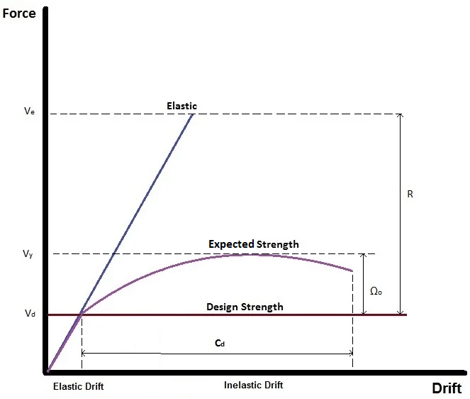
As I have taken classes in Seismic design there has seemed to be a bit of a discrepancy between the actual design theory, and what is industry standard with regards to overstrength. My understanding is that because the justification of using an R factor is based on the ductility of a material after yielding, that any element of the LFRS that is less ductile than the LFRS yielding element should be designed for overstrength. This is due to the yielding elements of an LFRS transferring more load than expected due to strain hardening of the material, conservation in design etc.

I have noticed that the R Value for wood shear walls is 6.5, is relatively high when compared to other LFRS (almost double that of an ordinary steel moment frame). This seems weird to me because a lot of other Wood based LFRS have very low R Values by comparison. Which leads me to think that it is not the wood but the nails themselves that are yielding in a shear wall. Because nails are super ductile, we are able to use a nice R Value of 6.5.

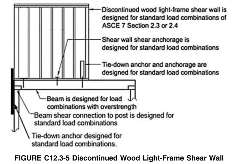
Building off of that, other elements of the LFRS that are more ductile than the nails (or would have the nails as their yielding element) would not need to have overstrength applied to them. For example a CS16 strap, HDU hold down (the device itself), A35 angle. Whereas any element of the LFRS that are not ductile like the nails should be designed with an overstrength factor. Examples of this would be an actual anchor into concrete (for an HDU or sill plate anchorage), a drag truss, a beam to which a hold down is strapped (along with the beam supports) etc. Is this reasoning correct?
main things that bugs me that seems to be “industry standard” is the often times overstrength is not applied to HDU anchors (like an SSTB bolt, cast in place rod, or epoxied anchor). Because of the nature of R factors and Overstrength it would seem that by not applying an overstrength factor we would be making the yielding element of our LFRS the brittle concrete. Which kind of undoes the while R factor thing.

I have heard people say that as long as our concrete anchor capacity is greater than the hold down capacity that we would be fine due to the hold down yielding before the concrete…which makes sense, my only concern for this would be that part the purpose of an overstrength factor is to account for strain hardening in the system. If the Hold down yields before the concrete…but then has strain hardening occur enough to increase the capacity to be greater than the concrete anchor, then the concrete anchor would be taking more load than it was designed for…thus causing a brittle element of our LFRS to control. This seems very wrong to me. I have also been told that Simpson accounts for this when reporting strength values for SSTB anchors, SHTD straps, PABs etc…is there any actual documentation for this though?

So…I guess my questions boil down to these two
1. Is it a safe assumption to say that most metallic connectors (like CS16 straps, HDUs, A35s, LTP4s, etc) are more ductile than a wood shear wall (or their yielding element is the nails) and thus do not need overstrength applied. (This would apply to FTAO straps…connecting a drag strut to the system via CS16 straps or LTP4/A35 plates, strapping over a cut in the top plate, etc).
2. Should we be designing concrete anchors in a shear wall system for a full overstrength factor? Or is there some justification to get around that?
 
Replies continue below

Recommended for you

Since nobody else responded, I'll give it a shot. I was hesitating to respond because I'm not an expert in this and was waiting for someone else to opine, but here goes.

From what I understand, the application of overstrength is when you have a vertical discontinuity in stiffness. The overstrength applies to the hold downs and the supporting elements (beams, slab, columns) below as well as their anchorages and collectors. The main times I think about this is something akin to a wood (or other) structure on a podium, or weird things like shear walls supported by beams. I'm not sure if this is the right way but I don't get as deep into it as you did. If there's a radical change to the lateral system on one floor to another, overstrength is getting applied. (By the way, I never apply it to a concrete cellar/basement, even though the same thing applies due to the extremely higher stiffness of that floor. It's just engineering judgment.)

Regarding your questions,
1. They would need overstrength applied when there is a change in stiffness. I don't think the ASCE 7 code makes the distinction about ductility that you're referring to. However, it's a bit wishy-washy and you can use your engineering judgment. For me, the only time I encountered this relating to wood was when I had a few stories of wood on a concrete podium. The holddowns connecting to the concrete slab were designed for overstrength. The slab itself and its columns were also designed for that, though that's not related to your question. If it was a wood structure below with something like portal frames and FTAO openings in a radically different configuration from above, then yes, I'd design all of those elements with overstrength. It would get very...messy. A lot of those don't have high capacities in the first place.
2. What is a concrete anchor in a shear wall system? If you mean a wood shear wall supported by a concrete shear wall, yes, I design the holddowns for overstrength.
 
To the OP. The overstrength factor as presented in academia is like a soft intro to capacity based design. I recall having left university wondering myself why we don't use overstrength on anything that is not the yielding element. In heavier construction, the overstrength often functions this way, capacity protected collector elements get overstrength as well as connections etc.

Now the concrete code, and steel code both recognize the need to capacity protect elements in ductile structural systems.

Then we have other code applications (ASCE) of overstrength alluded to by milkshakelake. There are various conditions causing discontinuities in the seismic system that trigger overstrength requirements. These conditions have been found to cause undue effects on the structure and also change it's dynamic behavior from the main behavior the code assumes. The outcome is that we have significantly more capacity at these elements to preclude their sudden failure during an earthquake, while somewhere else in the system yields.

Now on to wood shear walls. I cannot recall the papers , but my understanding is that the ductility is mostly on the yielding of the nails and damage in the shear panel itself. Not the tie down device.

However, and it's a big however, the anchorage of the tie down is by ACI Ch17. And in there there is a requirement to satisfy for both tension and shear seismic anchors that is related to ductility.

If concrete breakout is the controlling limit state, Then You get that sudden failure which is not good for seismic anchorage. So the code demands that you pick one option to 'protect' the anchorage. One option is to limit the force based on some yielding element that is ductile in the load path before the anchorage. Another option is to amplify the earthquake force components by overstrength.

The IBC code has an exception for this provision regarding sill plate anchorage bolts in shear, but for tension it is silent. Meaning designers are left having to select from ACI some behavior they think it's justified, or overstrength the hold downs.

Overstrength is easy to apply but might cause some big headaches in conventional construction. So, crushing of the sill plate is often used as justification for the maximum load that can be delivered to the hold down.

I am aware that many engineers. Even out here in seismic country don't think much about this on typical shearwalls. The effort coupled with manufacturer published ASD capacities makes it pretty easy to just move on.

 
As driftLimiter mentioned, there are specific provisions in ACI 318 about the need for overstrength for anchors (section 17.10.5.3 in 318-19). That section requires you to include overstrength unless you meet one of a few different requirements. There are 3 exceptions listed in that section:
a) your anchor bolts would fail in steel prior to concrete (with some reserve capacity in concrete and some additional prescriptive requirements)
b) there is a ductile yielding mechanisms and the anchor is capacity designed against that yield force increased by material overstrength and strain-hardening
c) there is a nonyielding mechanism and the anchor is capacity designed against that ultimate capacity (presumably including material overstrength). For this one, the commentary specifically mentions sill bolts where the crushing of wood limits the force that can be transferred to the bolt.

I don't think it's quite as straightforward as everything that is less ductile than the yielding mechanism of the LFRS requiring an overstrength factor and everything more ductile not requiring overstrength. I think that the overstrength factor is applied to specific things that the code wants to ensure don't yield/break. The code may not want them to yield/break because they are less ductile, but it may also be that those items yielding/breaking would prevent the LFRS from working as intended. For example, a braced frame connection may or may not be as ductile as the brace itself, but the system wants the braces to yield/buckle. And on the other hand, crushing of the wood sill isn't ductile, but the code writers have determined that a wood shear wall system still functions as intended even if that happens.
 
In the 'big picture', the overstrength factor is applied to ensure that the structure yields, or develops a plastic hinge, where it's expected to, and remains elastic elsewhere. IOW, it accounts for materials within the ductile failure zone that may be stronger than we anticipate, and other members may not be.
 
Holdowns to concrete need to be designed for overstrength or have an 8 diameter yielding section of anchor rod, and attachment to concrete capable of resisting this. For my designs, I just require the holdown standoff and all anchors are buried deep enough to be stronger than the rod with strain hardening.

Collectors and drag struts and diaphragm connections to collectors and walls are designed for 1.25 times the seismic load with certain irregularities per ASCE 7. I always include this factor. Clips on the shear wall are part of the system (assuming plywood stops at the underside of joists). I don't know, but my guess is that all these connectors have nails that can absorb energy and there is typically a lot of redundancy in a wood frame building. It may be worth designing for overstrength where there is clearly a single critical path.

Be sure to read the literature on straps nailed to SCL lumber, because often they have far less capacity. I don't have it at the moment, I believe there was a technical bulletin issued by Simpson that no one seems to know about.

 
This has been a topic of discussion in our office as well. We work primarily in SDC D, on the West Coast, so my thoughts are applicable to seismic regions where cracked concrete design is required. This discussion is also specific to wood-framed structures with flexible diaphragms. My take on your questions.
1. ASCE Ch. 12 has guidance stating that Ω should be applied to collector elements, however, there are exceptions for light-framed construction that essentially allow the designer to disregard Ω0. The exceptions are in different locations depending on which method you’re using to calculate the base shear.
2. Yes, concrete anchors should be designed using Ω except for shear anchors as discussed previously. (There are always exceptions)

I’d like to talk about #2 a bit more and would love to hear what others are doing in practice. I am not aware of any exceptions or outs to allow the designer to not include Ω.

I was recently on the Simpsons site looking at their anchor selector software. You can input your ASD load and parameters, including SDC, and it will provide a list of applicable HDs and corresponding anchors. Even though you enter your SDC they disregard Ω. I sent an inquiry to Simpson, and they replied basically saying that it’s the designer's responsibility to include Ω in their entered load.

Further, if using the SSTB bolts for residential applications, an SSTB24 is the largest anchor for a 6” stem wall (again, always exceptions and there are plenty of 8” basement walls – most residential stem walls are 6”). This would result in a maximum ASD tension capacity of ~1500 lb (3740/Ω=2.5).

Footnotes for PAB’s state that the anchorage conforms/complies to ACI 318-14 Section 17.2.3.4. I assume this means that they have made the footing so large that the steel is now the weakest link and thus concrete breakout is avoided. Obviously, most residential contractors are use to SSTBs and would have a few more words to say about engineers if we only specified PAB’s.

With all that said, what are the standards of practice for you, and what happens at your firm?
 
The best graphic I have related to seismic design is the following:
Seismic_ee9ofe.png


Note: I originally found this in a SEAoC presentation, I believe. Back when I worked for RISA, I gave it to someone to explain this concept to them. Eventually it made it's way into this page on RISA's website. Unfortunately, the RISA folks screwed up the image a lot. So much so that I can't believe they still have it posted. It just goes to show how little understanding of the subject they have there anymore. Supposedly, that image was posted when I still worked there 2016. So, I feel some responsibility for this image being so wrong. Though, in my defense, the 'sales' department may have taken the image and ran with it without seeking my input (or the input of anyone who actually understands seismic design).

 
Note: I was going to e-mail them and let them know that they've got something truly stupid on their website. But, that's problematic.
a) I now work for a competitor, so it's in my company's best interest that RISA continue to look incompetent.
b) The only person I know over there is the CEO (Amber) and she is the one who told me (through a 3rd party) that they would sue me if I talk about their products on social media. So, I really shouldn't call attention to this thread. LOL.

Also, below is the original Image. It turns out that the image was from a Structure Magazine article from the SEAoC Seismology Committee.
 
Regardless, I hope you all appreciate the simplicity of the curve in explaining seismic design. So much information presented in a pretty simple format.

1) Structures are not 'elastic' during a seismic event. Therefore, we take the seismic shear and divide it by R to get a 'design shear'. Where R is based on the expected ductility of the system.

2) That is great, but there are elements of the system (usually connections) that must be designed to a larger force in order for the system to achieve the expected ductility. That's what the Omega values are for conceptually.

3) Then we also have to realize that the inelastic drift is going to be significantly higher than the elastic drift. So, we account for this with the Cd multiplier.

Once you understand this conceptually, the rest of seismic design is just understanding the details on how we ensure the expected behavior can be achieved.
 
Thanks for all of the replies! This discussion helps a lot (sorry I am a little late replying myself). For some reference I am also in a Seismic Design Category D area.

I talked to one of my professors who specializes in seismic design about this a bit. We came to a similar conclusion to what a lot of you guys have talked about. Components that would prevent the LFRS from acting the way it was intended by yielding should be designed for over strength. For example if collector for a shear wall is unable to transfer the load elastically to the shearwall, then as the load develops in the structure the load will likely not ever make it to the shearwall...thus kind of defeating the purpose of the shearwall. Furthermore a hold down anchor into concrete would also be a situation where we would need to guarantee it would remain elastic throughout the seismic event. We could use an over strength factor on the anchor, or we could satisfy the provisions ofACI318-19 Ch 17 (as many of you have answered previously).

We talked a bit about designing the anchor to the capacity of the hold down device (say for example a Simpson HDU). If we can show that the hold down is the "weak link" then the provisions in ACI318-19 ch17 would be satisfied. But then that lead me to another question that we weren't really able to reach a conclusion on. And that is whether or not the hold down device itself(the HDU or whatever is being used) needs to be designed for over strength. From my experience at other firms, and talking with some engineers at other firms this is not done anywhere. So I assume there is some reasoning behind it, but to me it seems like the bucket yielding would make it so that the shear wall is no longer the yielding element of the LFRS, and thus no longer acting as intended...but maybe this was already considered when Simpson gave allowable loads for the hold downs(although Clerical Forensic's response makes me wonder a bit more about that), or maybe we are ok with the bucket being the weak link? I would imagine when APA did testing of shear walls they had hold down devices on them. This would make me think that the hold down devices (again, something like an HDU, not the concrete anchor) are kind of lumped in with the shear wall as the main "LFRS", and is thus ok to yield like the rest of the shear wall? I am curious to know what other people's thoughts are.

Also thanks for the graphic JoshPlumPE. That helps a lot.

My take aways from this so far are...

1. Straps and Ties that are not part of the primary LFRS system (like collectors or connectors for drag elements) should be designed for over strength, however things like FTAO straps that are part of the actual shear wall need not be designed for over strength.

2. At the least, concrete anchors for hold downs should be designed to the capacity of the hold down device connecting the anchor to the shear wall. (A few of you mentioned including some material over strength with the hold down capacity, what is a typical value you guys have used for that? Are we talking like, 15% more strength, or something on a much larger order of magnitude?).

Thanks again for all of the wisdom! I have learned a lot from this discussion so far.
 
In AISC 341 (the seismic code for steel systems), they give prescriptions for this increase you're talking about in point number 2. This varies based on the grade of steel you are using, and they lay it all out for you so there is no guessing. This is usually deemed "Ry" and you multiply it by Fy, or your yield strength. This gives you an "expected" yield strength in our jargon.
 
The SEAOC Blue Book 2019 Version has a section that addresses overstrength requirements for light frame shear wall hold downs that you may find interesting. This document also mentions and old ASCE 7-
02 definition of hold downs that is (was) useful in this discussion.

hold-downs “are intended to resist load
without significant slip between the device and the shear wall boundary element or be shown with cyclic testing to
not reduce the wall capacity or ductility.”


It does say that the anchorage is designed per the requirements of ACI Ch17 (i.e. overstrength or capacity based).

In my experience this isn't being done.

I've heard some say the crushing of the sill plate on the compression chord can be used to limit the anchorage force required, I've never gone and explicitly tried it.
Next time I am working on this, I may take a look at the crushing analogy and see how it pans out.

 
driftLimiter thanks for this info. JoshPlumPE, thanks for the graphic.

For our firm’s discussion, I am narrowing the scope to light-framed construction to meet the exemptions to avoid using overstrength for the collectors and focusing on the topic of overstrength and the anchor that attaches to the holdown.

I agree, I don’t believe it is standard practice for overstrength to be used for smaller projects (residential) for cast-in anchors such as an SSTB.

We’ve run some back-of-the-envelope calculations to see if we could find a weak link. One of the problems was finding the failure values for things like sheathing, wood crushing, or even the connection of the HD to the wood. Some threads here point to information for the factor of safety used in the NDS, but those publications lead to an estimate. I’m not aware of Simpson publishing the actual average failure value for the holdowns. Without that information, there is little to hang your hat on if your goal is to find a weak link elsewhere. All of this led us back to simply applying overstrength to the anchor.

I do find it interesting that the commentary of the ASCE 7-16 Figure C12.3-5 Discontinued Wood Light-Framed Shear Wall states that the holdown is designed for standard loads while the supporting beam is designed using overstrength. This would lead me to believe that holdown and attachment on all levels need not be designed using overstrength. EDTT: As Sandman21 pointed out structures braced entirely by wood light-framed shear walls are exempt from overstrength 12.10.2.1. The figure is specific to vertical irregularities which is 12.10.1.1.

Fig._C12.3-5_yy05jz.png
 
An SSTB is a tested product and does not derive its capacity from ch 17. We do not use SSTB's at all and use PAB and never hear any complaints about whatever "issue" they think they have with the anchors. Only two items are except from 17.10.5 requirements, in-plane sill and out-of-plane anchors, 1905.1.7. All other anchors need to comply with the requirements in 17.10.5. Selecting PAB or other product which exceeds the allowable load of the holddown. Your holddown is the ductile element transmitting loads to the anchor.

kurichan said:
Components that would prevent the LFRS from acting the way it was intended by yielding should be designed for over strength. For example if collector for a shear wall is unable to transfer the load elastically to the shearwall, then as the load develops in the structure the load will likely not ever make it to the shearwall...thus kind of defeating the purpose of the shearwall. Furthermore a hold down anchor into concrete would also be a situation where we would need to guarantee it would remain elastic throughout the seismic event. We could use an over strength factor on the anchor, or we could satisfy the provisions ofACI318-19 Ch 17 (as many of you have answered previously).

Over strength does NOT ensure that the collector remains elastic, you would need to have an over strength equal to R. In the case of wood shear walls likely larger.

kurichan said:
We talked a bit about designing the anchor to the capacity of the hold down device (say for example a Simpson HDU). If we can show that the hold down is the "weak link" then the provisions in ACI318-19 ch17 would be satisfied. But then that lead me to another question that we weren't really able to reach a conclusion on. And that is whether or not the hold down device itself(the HDU or whatever is being used) needs to be designed for over strength.

The holddown is not designed for over strength, see ASCE7-16 12.10.2.1, this has been long established in many code cycles and the provisions for light-framed wood construction are unchanged, your professor should be aware of that.

kurichan said:
1. Straps and Ties that are not part of the primary LFRS system (like collectors or connectors for drag elements) should be designed for over strength, however things like FTAO straps that are part of the actual shear wall need not be designed for over strength.

Light-framed buildings are exception from over strength requirements. I also don't understand your logic here, FTAO would be more critical to the behavior of the shear wall and would be more likely to have overstrength.


Wood shear walls are highly ductile and redundant systems, so much so that non-license people can design them.

 
Clerical Forensics said:
Are you suggesting that overstrength is not required because anchor calculations are not required due to it being a tested product?

No, just pointy out that an SSTB is not covered by Ch. 17.1.2. Just like LSTHD/STHD these are tested products outside the scope of ACI even thought they are embeded in concrete. Wood design has a long history of providing safe redundant performance. When using items such as SSTB, LSTHD, etc. are used on houses that are likely to be exempted from seismic requirements or per conventional framing requirements, 1613.1.
 
sandman21 said:
No, just pointy out that an SSTB is not covered by Ch. 17.1.2. Just like LSTHD/STHD these are tested products outside the scope of ACI even thought they are embeded in concrete. Wood design has a long history of providing safe redundant performance. When using items such as SSTB, LSTHD, etc. are used on houses that are likely to be exempted from seismic requirements or per conventional framing requirements, 1613.1.

As I see it, the exception of 1613.1 forwards you to 2308. 2308.2.1 limits the designer to one story, in SDC D. So that doesn't help in my search for a codified statement.

Now I am wondering if using an anchor that is a tested assembly, anchor calculations are not required thus Ch. 17 isn't required. In other words, overstrength is not required when using a tested assembly. Edit: I believe this is incorrect. There are tested assemblies that do required overstrength such as epoxy. However, the ICC report for epoxy points to Ch 17 while it does not for SSTBs.

sandman21 said:
We do not use SSTB's at all and use PAB...
Do you include overstrength in your tension loads when selecting a PAB? Edit: Still curious but I believe this is not required due to the ICC report mentioning steel governing and compliance with Ch.17
 
Status
Not open for further replies.
Back
Top