Continue to Site

Eng-Tips is the largest engineering community on the Internet

Intelligent Work Forums for Engineering Professionals

  • Congratulations KootK on being selected by the Eng-Tips community for having the most helpful posts in the forums last week. Way to Go!

Select Coilover Spring Rate by Available Wheel Bump Load = Peak Braking/Acceleration Load? 3

Status
Not open for further replies.

ErikPSS

Mechanical
May 16, 2020
18
In my last post, I solved for coil bind at full shock compression. It was an interesting exploration of that limit, but helpful replies by Greg and Brian pointed out the trike would be terminally undersprung at high accel/decel, so I am returning to the more traditional approach of solving for spring rate setting available wheel bump load to equal expected peak load under braking (front) and acceleration (rear).

Per my last post, I am seeking to minimize spring rate without riding on the bumpstops. To do so, remaining wheel bump load available at laden shock travel must be greater than expected peak compression load.
I would greatly appreciate any review of the following. Excel attached.

Load Estimates
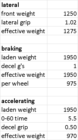
Brake: 1950lbm laden weight * 1g braking decel = 1950lb, divide by 2 front wheels = 975lb per wheel
Accelerate: 0-60mph in 5.5sec. (2.7g per second of 0-60) divide by 5.5sec = 0.5g * 1950lbm = 970lb on single rear wheel
Cornering at 1.02g???
load_zad08e.png


Shock Sizing
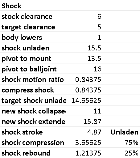
Current unladen ground clearance is 6"; target unladen clearance is 5" = body should lower 1".
To find motion ratio, divide lower A-arm pivot to shock mount (13.5") by pivot to balljoint (16") = 0.84. 1" lower @ wheel = 0.84" shorter shock.
Current shock compresses to 15.5" unladen, subtract 0.84" to find new unladen shock length of 14.7".
New shock collapses to 11", stroke of 4.87" extends to 15.87". Compressed to 14.7" unladen is 75% compression travel (3.7"), 25% extension travel (1.21").
shock_left_r37pyf.png


Unladen Weight
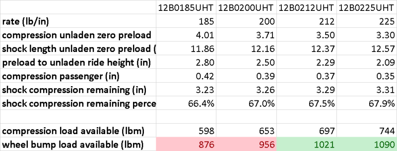
Total weight unladen 1740lbm; corner weight unladen 570lbm minus 60lbm wheel & suspension = 505lbm sprung.
Spring angle of 54deg. Find spring angle adjustment factor by SIN(54deg in rad); multiply by shock motion ratio of 0.84 = corrected spring motion ratio of 0.68.
Sprung weight of 505lbm at wheel divided by 0.68 = 740lb at the spring.
740lb divided by 212lb/in spring = 3.5" compression at zero preload. 15.87" extended shock compresses to 12.4".
Target unladen shock extension is 14.7", subtract 12.4" = 2.3" preload to extend shock to target ride height.

Laden Weight
Front corner weight when laden = 625lbm, subtract unladen corner weight of 570lbm = 55lbm of added passenger weight, divide by spring motion ratio of 0.68 = 78lb at the spring, divide by 212lb/in = 0.37" compression.
Unladen shock compression travel of 3.7" minus 0.37" = 3.3" (67.5%, nice!) remaining shock compression travel when laden.
3.3" remaining shock compression travel * 212lb/in = 697lb at the spring, divide by spring motion ratio of 0.68 = 1020lb available bump load at the wheel
1020lb available at the wheel > 970lb expected when braking at 1g
front_left_mga8hn.png
 
Replies continue below

Recommended for you

I only have a minute (I have "real work" to do) but the assumption of complete weight transfer to the front under braking is making some assumptions about the center of gravity height and the amount of traction available that may not necessarily be valid. The ratio of center of gravity height to wheelbase needs to be in the fore/aft weight transfer calculation somehow, and the ratio of center of gravity height to track width needs to be in the lateral weight transfer calculation somehow.

We never got into the rear suspension on the other thread, but if this vehicle has the usual chain or belt drive to the rear wheel with a swing-arm (motorcycle rear suspension) the geometry of the suspension leads to some anti-squat effects that are really messy to calculate because the chain-pull force comes into play, and the swing-arm pivot height relative to the wheel center-line comes into play. I don't calculate it ... I just know what swing-arm down angle I want in order to get the results that I want, and what symptoms to look for in how the bike functions. BUT. We have suspension cornering loads on the suspension that are very different from yours.
 
Perhaps you should consider some sort of displacement input at the tire contact patch(es) in addition to these inertial force-transfer effects from the sprung mass side . . .


Norm.
 
OK, I know nothing about trikes but find this interesting and have some naïve questions I you don't mind.

@NormPeterson, you mention contact patch. Do trikes have the necessity for a camber adjustment for the rear tires? Camberplates? A torch on a straight axle?

I've never driven or rode on a trike but from observation they obviously have very different lean or roll characteristics from a motorcycle so do trikes have a roll center of any kind? Triangulated maybe?

Finally, what effect can track width have on the suspension of a trike? I cant offer any explanation for this but I'm imagining there could be some benefit from angling coilovers towards the centerline of a trike. Bad imagination?

I've always been told the only stupid questions are the ones you don't ask. [smile]
 
The vehicle in question has two wheels in front and one in rear. (Think Can-Am Spyder or Polaris Slingshot, or something really similar.) The front suspension is upper and lower wishbone with theoretical adjustment although I don't know how much adjustment capability is designed in. The rear suspension, single rear wheel, is pure trailing arm, motorcycle suspension geometry. The front suspension will have instant-centers and force-based roll center just like a similar upper-and-lower-wishbone front suspension of a four-wheeled car. The main difference is that the front suspension has to take care of ALL of the load transfer from cornering, as the rear suspension (single rear wheel) cannot contribute any roll stiffness whatsoever.

Track width reduces roll-over propensity. The Can-Am and the Polaris are wiiiiide because of this.

The "trikes" that you are thinking of - single front wheel and two rear - are just plain awful.
 
Brian,

Thanks for the explanation. I made a bad assumption but I have a much better idea of what this about. Thanks again.
 
Brian: Indeed, but for a zeroth-order approximation, your suggestion to solve for compression load was an improvement over my idea to solve for coil bind. For example, the stock springs are rumored to be 225lb/in, and estimating for load gives 212lb/in. Though not causal, this could be the difference between stock shock compression travel with thick bumpstops versus my estimate above using a full shock stroke.

The rear is quite a bit messier. I suspect it is over-sprung to reduce travel to maintain ground clearance and because the belt drive sprocket is not concentric with the swingarm pivot: as the swingarm travels in compression, belt tension increases.

And you are correct: Polaris Slingshot. I plan to widen the front track by 12% from 69.1" to 77.5".

I'm actually hoping for review of the fundamental shock and spring geometry calculations. The load approximations are, as above, zero-order.
 
Erik,

Again please excuse a stupid question. I'm not familiar with trikes. I am a bit familiar with suspension tuning though. I'm curious about why, unless I've lost it in your terminology, you haven't said anything about your wheel rate? Maybe this is what you're referring to with bump load? Anyway, you've left out your wishbone linkage ratios which gives you your spring rate at the wheel. Adjustable wishbones can control your spring rate at the wheel and your ride frequency. Again, my apologies if this is all nonsense.
 
RRiver,

Please don't apologize, as I am the least experienced and knowledgeable, and will undoubtedly learn more from your questions than you will from my answers. My only experience with suspension tuning is with off-road trucks, which use a colloquial (redneck) terminology.

You are correct that I am using "at wheel" and "wheel bump load" to refer to force at the wheel, which I should have notated as "lbf" instead of "lbm". This approach (solving for expected load at the wheel) solves for spring rate at the coilover, and does not involve finding wheel rate.

Regarding those wheel rates, or more specifically, the motion ratios, I am curious if the following is correct:
To find motion ratio, divide lower A-arm pivot to shock mount (13.5") by pivot to balljoint (16") = 0.84. 1" lower @ wheel = 0.84" shorter shock.
Spring angle of 54deg. Find spring angle adjustment factor by SIN(54deg in rad); multiply by shock motion ratio of 0.84 = corrected spring motion ratio of 0.68.
 
@Erik,

I can tell you what I've used:

Wheel Rate = Spring rate (a\b)^2 x (c\d)^2

a = Distance from lower control arm pivot to where the spring acts on the lower control arm
b = Length from lower control arm ball joint pivot to inner pivots
c = Distance from lower ball joint pivot to front suspension instant center
d = Distance from the center of the tire contact patch center to front suspension instant center

Example:

Spring Rate = 500 lbs.-in
a = 9"
b = 14"
c = 90" +\- 1\16"
d = 94" +\- 1\16"
Wheel Rate = 188 lbs.-in or a wheel rate at 37% of the spring rate

Assuming the same example above but the lower control arm is moved out 1". a and b are now 10" and 15". The Wheel rate is now 230 lbs. or 46% of the Spring Rate.

This is just an easy example and yes you can use the trig. Just remember it's at the lower control arm pivot point height. I would suggest doing it with a tape measure at first though to visualize what you're measuring. It also shows what's happening with un-sprung weight and how linkage effects it. This may also be why Norm brought up the contact patch? I cant speak for him.

Hope this helps.
 
Erik,

I went to a Slingshot forum and tracked down some parts assembly prints and I hate to be the bearer of bad news but I think you're spinning your wheels. No one on the forum pursuing performance has solved the problems you're having. After reviewing the prints I can see why. I honestly couldn't believe it when I saw that the control arms are bolted directly to the frame and the pivot bosses are kept off the frame and adjusted with shim packs. You might want to ask Norm with his bike experience how to feel for developing vibration issues as you put some miles on your machine. Sorry to be so negative but I'm laying here recovering from an infected hip replacement with way too much time on my hands and found your questions interesting. Myself, if I didn't have them I'd get a tig welder, some chrome moly pipe, some plate and a tube bender and have a great time when I can get up and about with this virus in charge now. I also don't see how to send private messages on this site which I would have done.
 
I would think a spring angle (squared) effect would also be involved in the motion ratio, and I think that referencing spring angle to the vertical and using the cosine makes more sense because it's a vertical effect we're looking for here. Squared because the spring force has to be greater than the vertical force at the lower arm and the spring's axial displacement less than the vertical movement at the spring's lower arm pickup. Generally a small component of motion ratio (i.e. close to 1.0) for cars so the folks who seem to use cosine(spring angle) not squared aren't going to be off enough to much matter. Probably not negligible here.

So, (arm ratio) x (FVIC ratio) x (spring angle), the whole product squared for rate calcs.


I mentioned 'at the contact patch' with reference to some amount of upward displacement input that can only come from the road surface. When you hit a bump (or perhaps an unavoidable board or something) at speed you're going to get upward wheel displacement that's going to use up some amount of bump travel. Chances are, you'd also be on the brakes using up some more 'bump' travel from the inertial effect (forward load transfer).


Norm

 
Norm,

Great explanation. Thank you. You're absolutely right about the spring angle but honestly, I have a hard time visualizing what I'm seeing compared to the actual skewed photos I can find leaving me with a lot of questions. Mainly the ball joints seem to be on a different axis. It's a relationship I'm not at all familiar with and I don't want to mistakenly offer bad information.

slingshot_btexec.png
 
Thanks River and Norm. If you're curious about the selection criteria and some brief semi-informed analysis of the vehicle, I'm happy to post it. In short, it's a deliberate handicap, but it makes going slow feel fast.

If I could ask a related question (since it will determine damper travel at ride height):
Since I wrote the spreadsheet to calculate these values, it was easy to test various damper sizes.
My present calculations with the Bilstein AS2 high-pressure gas monotube yield unladen compression travel of 3.7" (75%) and rebound travel of 1.2" (25%), compressing when laden 2/3rds : 1/3rd. With light springs on a light vehicle, I am concerned that the high (by percentage of total) gas spring effect (50-100lbf) will inhibit micro-surface compliance.
The Bilstein XVA is the equivalent damper which allows for ultra-low rod pressure, but ride height would put the damper at unladen compression travel 2.7" (56%) and rebound travel of 2.2" (44%), compressing when laden to 50:50.
Riding with the damper in the center of travel in the rear would also be beneficial to minimize change in tension on the drive belt. I suspect either damper could be designed around.
Which would you select for this application? I suspect linear valving would be preferable with the limited compression available at 50:50 travel.
 
 https://files.engineering.com/getfile.aspx?folder=b2027c89-159b-49f3-bbbd-eb5fced4ff1f&file=suspension.xlsx
Status
Not open for further replies.

Part and Inventory Search

Sponsor