Continue to Site

Eng-Tips is the largest engineering community on the Internet

Intelligent Work Forums for Engineering Professionals

  • Congratulations KootK on being selected by the Eng-Tips community for having the most helpful posts in the forums last week. Way to Go!

Select point or edge Features from Cylinder

Status
Not open for further replies.

Maxgo

Industrial
Sep 15, 2023
3
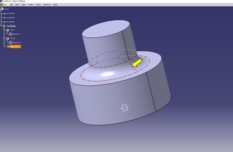
Hello, I have just start again working with CATIA V5 after some years and I don't remember the following behavior. Let me start with a simple explanation, I can't select the edges or points in a cylindrical or edge fillet feature, see the example with the edge fillet, but also applied to the cylinders:
4_c23ito.jpg


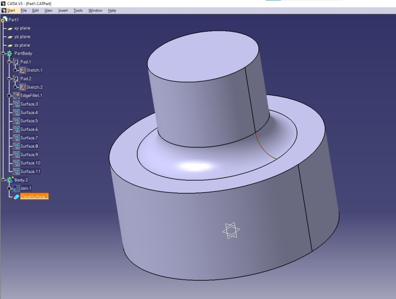
The complete feature is selected, instead the edge only or a point. I have converted to surfaces, disassemble and solidify again and then is possible to select the edges and points
1_uineyp.jpg


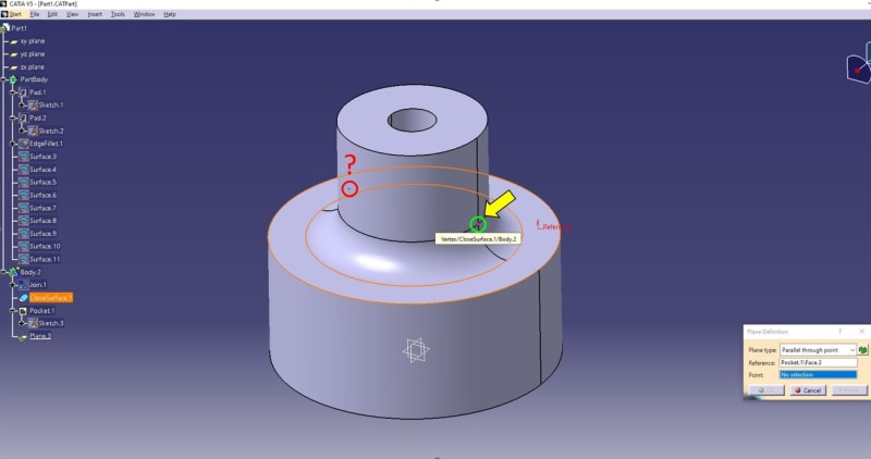
but I have realized that if I try to use the point, for example, to create a plane, there are 2 points selected
5_dftcvl.jpg


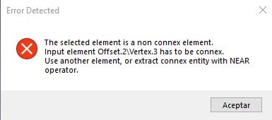
and then, an error pops up

6_l3j0o3.jpg


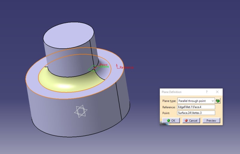
I have tried to reset to defaults, user selection filter has nothing selected... The only "solution" is to isolate the feature as surface, then disassemble and use that point
7_nmltda.jpg


But I think, this wasn't this way in the past. This is the rev.

8_necfeb.jpg


Is there anything to activate or de-activate, I don't see any option...

Thanks in advance.
 
Replies continue below

Recommended for you

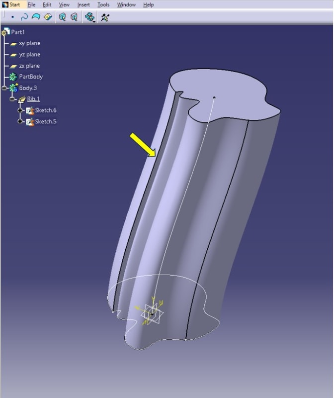
Update, I have detected also that other features have this issue, I created a rib using a spline geometry, and you can't select a shapr edge if you want to edge fillet that, see example:

9_bswia5.jpg


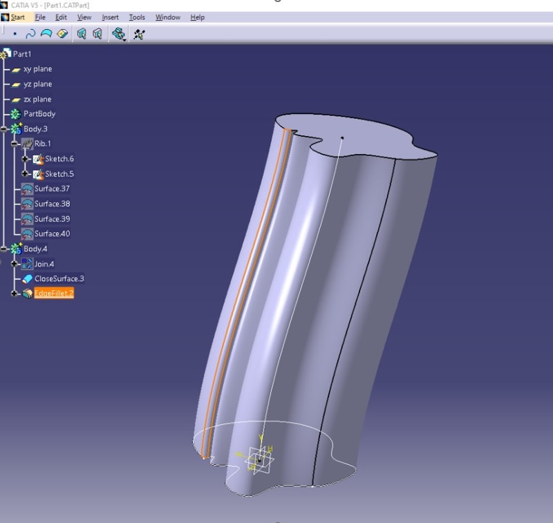
the complete rib is selected instead, I can`t believe that for each step we have to switch to shape design, solidify again, and so on... because in that way it works

10_r56xpn.jpg


Thanks again...
 
Hi.

Is is a way how geometrical modeler works. Not all edges are "real" and are displayed because of technical reasons, not to be used by a user.
Also it is true that some rotational features have ambiguities.
 
Hi, thanks for answer, then, the only solution for the rib example to make the sharp edge selectable for making a edge fillet is to go to shape design, disassemble it and close again in part design? There is no other option in CATIA for making all the features "selectables" without disassemble the solid?

Thanks in advance.
 
If you are just looking to get a plane at the height of the tangent on fillet.
Plane Parallel through point should work.
Pick planar surface and rmb on point input box, then choose create point, on curve or circle center (select the curve that represents the diameter not the fillet). No need to extract a surface.

If you were to break your circle in your sketch into two half circles you will get what you want.
Same with the spline, if sketch was a spline and a line, or two splines.
I believe with catia on a full circle there is no "true" start/stop.
It adds the two u or v lines for graphical representation.
 
Building geometry on BREP, and especially soft edge or vertices are often a source of update error during geometry modification.

Can you describe why you need to select those soft edges or vertices and I will try to provide a more robust way to get the geometry you need.

Eric N.
indocti discant et ament meminisse periti
 
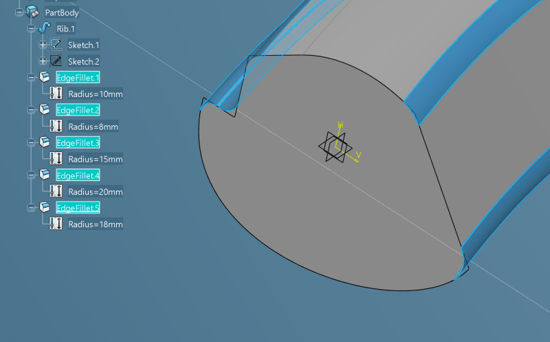
I could not reproduce your rib problem. Using 3DX on the cloud i was able to fillet any hard edge.

2023-09-18_9-13-10_nxat1b.png


Can you start catia with OOTB catseting?

Eric N.
indocti discant et ament meminisse periti
 
I noticed one thing, and that is that you are using hybrid-modelling... i.e solids and sufaces/joins coexist in same (solid) bodies... normal modus operandi is to have geometrical sets for surfaces/points and bodies for solid features.

regards,
LWolf
 
Status
Not open for further replies.

Part and Inventory Search

Sponsor