Continue to Site

Eng-Tips is the largest engineering community on the Internet

Intelligent Work Forums for Engineering Professionals

  • Congratulations KootK on being selected by the Eng-Tips community for having the most helpful posts in the forums last week. Way to Go!

Self Contained Sluice Gate - Actuator Stall Load 4

Status
Not open for further replies.

JoelTXCive

Civil/Environmental
Jul 24, 2016
921
I'm designing the anchor bolts for a self contained sluice gate with a motor controlled actuator.

These are 10x10 gates that have a self weight around 20 kips. The stall load of the 7.5hp motor is 300 kips due to all the mechanical advantage of the actuator's gearbox.

I have the tension/compression loads due to water pressure worked out, but have a question regarding how the gate load is transferred to the supporting structure.

This morning, a mechanical engineer told me the self contained gate sends no load to the supporting structure other than self weight.

I agree with this statement for normal operations; but not for a 'stuck gate' scenario.

Normal Operation
Under normal operation, the self weight of the gate is carried by the anchor bolts in shear. When the motor turns on the stem is in tension and the yoke beam receives a point load. Neglecting friction, the net load to the anchor bolts does not change.

'Stuck Gate' Situation
If the gate gets hung up; then the motor will continue to pull until it reaches the stall load.
Assuming nothing breaks in the gate; the full stall load (300 kips) will get sent to the anchor bolts.
In my mind, the gate frame will attempt to close up like a clam shell in this condition. The full 300 kips will be carried in shear by the anchor bolts.

Question (or Confirmation of my logic)
Do I need to design the anchor bolts to handle the full stall load of the motor?
Or, is my logic wrong; and no load gets sent to the structure?
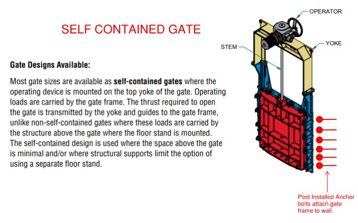
Sluice_Gate_Diagram_uo10cd.jpg


Thank you in advance.
 
Replies continue below

Recommended for you

I think the ME is right. The reactions are all still following the same load path, they just jump up to be a lot higher. You end up with a 150k compressive force in each side of the yoke, and the numbers will still balance. (300k up on the gate results in 25k/anchor up; 300k down from the operator gets transferred through and down the yoke to the anchors for 25k/anchor...assuming 12 anchors).

If this wasn't self contained, then yes....you'd be looking at a 300k load on the anchors below and a 300 kip reaction from the operator above that would have to be resolved through the surrounding structure.
 
Pham...so I think what the mechanical engineer was saying was INCORRECT.

The mechanical engineer was saying all the internal loads cancel out.

What I'm saying (and I think you are in agreement), is that the motor load IS getting transferred to the anchor bolts (the structure). (25kip per anchor in our example)

 
I got that. And I disagree with you.

Summation of forces in the Y:

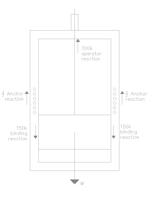
W+Binding Reaction-Anchor Reaction-Operator Reaction=0 .
W+Binding Reaction=Anchor Reaction+Operator Reaction
W+2(150K)=Anchor Reaction+300k
W=Anchor Reaction

boundgate_vxyswy.png
 
If the gate is crumpling, you have bigger problems than mounting.
 
Another way of looking at it: if this were not bolted to a wall and it were to bind, would it start moving across the table? No, because there's no net external force.

The clam shell thought is certainly valid, but that's a result of the eccentricity between the yoke and the stem. So long as the yoke is sufficiently stiff to prevent distortions or significant deflections, you'll end up with an insignificant (but probably non-zero) change in anchor shear.
 
Of course, if it gets stuck the structure and/or anchor bolts will carry that stuck load. This is similar to pulling cables in cable tray, if cable gets stuck, motor will keep trying to spin until the beam/cable/anchor bolt fail which ever comes 1st and it has happened a few times from what I hear.

Curious why it needs motor though, we just installed several sluice gates like that in our plant with no need for a motor (motor requires power).
 
AskTooMuch - that's true only if the motor and the gate are mounted independently. In that case, the only load path is through the anchors. In this case, the load path is through the 'self contained' steel yoke.
 
I dont agree, I'll get back in this thread later after others posted. For now it still looks to me the 300k "stuck loads" is transferring to the anchor bolt.
 
Agree with phamENG: the loads are entirely resolved internally. Maybe I am on glue but in order for the shear to flow through the anchors in the stuck position the entire assembly will need to want to lift up right? Well, the force is net 0 vertically due to the binding just offsetting the winch force (with bolts originally taking the W) so I dont see that being possible.
 
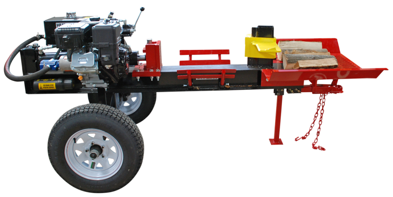
It's like a big wood splitter in reverse. How much are the wheels working when it's pressing through a hard piece of wood?

HWS1316-Wood-Splitter_zbj7pj.png
 
Asktomuch......We have back-up handwheel attachments on the gates. According to the mechanical engineers, it will take 68,000+ revolutions of the crank to open 1 gate. That will make for a long day.

North_Pump_Station_2020_01_09_02_gv5pho.jpg
 
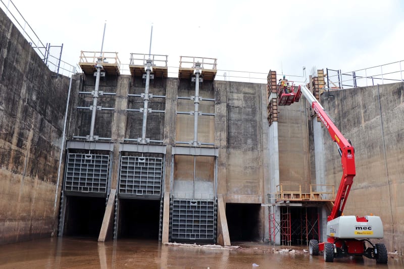
That's a pretty impressive gate lineup. And come on...you can't spin a wheel at 2.36 revs per second for 8 hours straight?

For anyone who thinks there's stuck load on the anchors....can you provide a FBD that shows the additional reaction?
 
Sbisteel.....That is a good visual. I'm 90% with you and Pham. Let me think on it.

That photo is from an older project. The current one has 6 10x10's and my retaining walls are 40ft tall. It's the biggest levee penetration and outfall I have done.
 
I agree with above about the reaction be resolved internally but there is some loading the anchors will see so dont skimp on them. The cost of anchors is nothing on a project like this. That load may be incidental like a log get caught up or due to eccentricity in the gate helped with some log getting stuck. You gotta watch out for those pesky logs.
 
The picture of the gates above are not self contained gates. The vertical forces on those cantilevered slabs are going to be immense. As a matter of fact, I question if they're adequate. But it's apples and log splitters.
As far as the number of turns to open those big gates, most plants have rigged up unapproved assists, like chain saws or similar to open or close those big gates. Once they get them started, they use a mechanical device to turn the other 67,999 turns.
 
Those are self-contained units. The gate is pulled up to the steel beam just above the gate. The jacking tension does not go up to the motor.
 
Based on the size of the yoke they are self contained. I would be curious how the operator works. Is that a torque tube or an extended pedestal?
 
Status
Not open for further replies.

Part and Inventory Search

Sponsor