Eng-Tips is the largest engineering community on the Internet

Intelligent Work Forums for Engineering Professionals

  • Congratulations waross on being selected by the Eng-Tips community for having the most helpful posts in the forums last week. Way to Go!

Sell element with solid extrude

Status
Not open for further replies.

Tinni1

Civil/Environmental
Sep 27, 2021
157
IE
Hello,

I am trying to model one bolted shear lab connection in cold-formed steel using Abaqus based on the literature.
In order to accurately capture the localized bearing of the bolts against the cold-formed steel Guidance has been provided below:

'shell elements are employed for the modeling of the material away from the bolt holes, while solid elements are used for the modeling of the bolts and the cold-formed steel sheet around the bolt holes. Rectangular openings are made in the shell element mesh around the bolt holes; the openings are then filled with solid elements using the *EXTRUDE command in ABAQUS'. S4R elements are used for the shell elements and C3D8R brick elements have been used for the solid part.

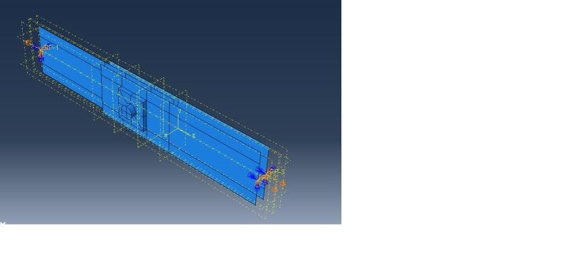
Following the above guidelines, I have modeled the plate, i.e First I created a shell planner model using the rectangular opening following this with solid extrude command I have created the inside rectangular solid block, in the part module in Abaqus. In the property module, I have assigned solid element types for the rectangular block inside and shell element type for the rest of the plate portion.

But while meshing I am not able to select the solid elements separately. I can only select the shell element part, which has been assigned S4R mesh. But I am not able to verify whether the solid element part has been assigned the C3D8R element or not, neither I am able to assign any element type as I am not able to select that part.

The picture of my model is attached in the below link.

[URL unfurl="true"]https://res.cloudinary.com/engineering-com/raw/upload/v1666294353/tips/Plate_with_solid_block_ww2pvr.docx[/url]
Could anyone please advise if my modeling technique is correct and then how I can verify and assign element type for the solid rectangular block?

Many thanks!
 
Replies continue below

Recommended for you

I can't personally verify your modelling choices however I have to ask, why not model the whole plate using shell elements? is the guideline that you just posted that recommends using both solid and shell elements retrieved from a recent published paper?
 
Hi,
I am not sure weather I understood correctly or not.
Could you try using Tools-->query--->element---->pick the solid element
It should show in the message area at the bottom.

Otherwise, create a copy mesh part as a orphan mesh. I think you can see the assigned element there.

Thanks,
 
If it's a single part with solid and shell regions and the sections are applied properly, the mesher will automatically assign solid and shell elements to those regions. Query tools will show you which (and how many) elements are included in the mesh and which region has which type of element. You can even enable coloring based on the element type.

If those were separate parts, you could connect them with a shell-to-solid coupling constraint.
 
Hello both,

Thanks for your response and suggestions.
Now I have modeled the shell part and the solid part separately and defined a shell-to-solid coupling constraint.
@ FEA way,
I am referring to the below paper published in 2022:
'A practical numerical model for thin-walled steel connections and built-up members'


Below guidance is provided for numerical modeling of the connection part:
' Shell elements are typically preferred over continuum elements for the modeling of cold-formed steel structural members due to their high computational efficiency. However, solid elements can provide a more
detailed and accurate replication of localised bearing phenomena. Therefore, for the FE model introduced herein and shown in Fig. 6, shell elements are employed for the modeling of the material away from the
bolt holes, while solid elements are used for the modeling of the bolts and the cold-formed steel sheet around the bolt holes, in order to accurately capture the localized bearing of the bolts against the cold-formed steel.'

However, I have a further question as below:
If I am connecting a cold-formed steel plate (thickness 2 mm) with a hot rolled steel plate of thickness 12 mm, with M10 bolts, then for the hot rolled steel plate modeling I could easily use only solid elements. Would it be numerically good to use shell elements for the 12 mm thick plate for the parts away from the bolt and solid elements near the bolt?

Could you please provide any guidance/recommendation on this?

Many thanks!
 
The model is rather simple so it would be best to try both approaches and compare the results. However, the approach with mixed mesh seems to be reasonable in this case and you just have to make sure that the transition is away from the region of interest.
 
You are welcome!

In addition to the method what FEA way mentioned,

Method-1: Shell to solid coupling.

Method-2: You can buried one row of shell elements inside the solid elements to avoid the additional DOF at the junction.

Thanks!
 
Great!, I will try both options.

Just two queries about the method2,
1. Burying one row of shell elements inside the solid elements, does that mean I need no coupling between the shell and solid elements?
2. Could it cause any overcloser issue, as in the buried portion the thickness of the shell and solid elements are both presents?

Many thanks!
 
Hello,

I followed the shell-to-solid coupling procedure for this problem.

My analysis step is dynamic and explicit. But when I ran my analysis, the analysis was aborted and I got the below error message:

'Degree of freedom 11 and at least one of degrees of freedom 1 thru 6 must be active in the model for *dynamic temp-disp. Check the procedure and element types used in this model'


I have applied displacement-controlled loading. The picture of my model is below:
Shell_to_solid_coupling_qj29nh.jpg

Could anyone please advise how I could get rid of this error?
 
You are trying to run a coupled thermo-mechanical analysis in Abaqus/Explicit and for that, you need elements with thermal DOFs (of coupled temperature-displacement type).
 
Hello, thanks for your response.

I have below two questions:

1. I have not applied any thermal load in this model, then how this analysis becomes a coupled thermo-mechanical analysis? Is that because of the shell-to-solid coupling constraint?

2. I changed the element type to coupled temperature displacement type. For this, it requires a thermal conductivity and specific heat property definition. My units are N, mm, and sec in Abaqus. What unit I should use for conductivity and specific heat in Abaqus?

3. Would it be possible to provide any reference from which I could refer to the specific heat and thermal conductivity values of hot-rolled steel and cold-formed steel? I am not familiar with thermal analysis, hence asking for this information.

Many thanks!


Apparently, you selected the *Dynamic, temperature-displacement step. That’s what the error message indicates. If you don’t want to include theat transfer in the analysis, change the step type to *Dynamic. Then you won’t need the thermal properties.
 
Status
Not open for further replies.

Part and Inventory Search

Sponsor

Back
Top