Hello,
I am trying to model one bolted shear lab connection in cold-formed steel using Abaqus based on the literature.
In order to accurately capture the localized bearing of the bolts against the cold-formed steel Guidance has been provided below:
'shell elements are employed for the modeling of the material away from the bolt holes, while solid elements are used for the modeling of the bolts and the cold-formed steel sheet around the bolt holes. Rectangular openings are made in the shell element mesh around the bolt holes; the openings are then filled with solid elements using the *EXTRUDE command in ABAQUS'. S4R elements are used for the shell elements and C3D8R brick elements have been used for the solid part.
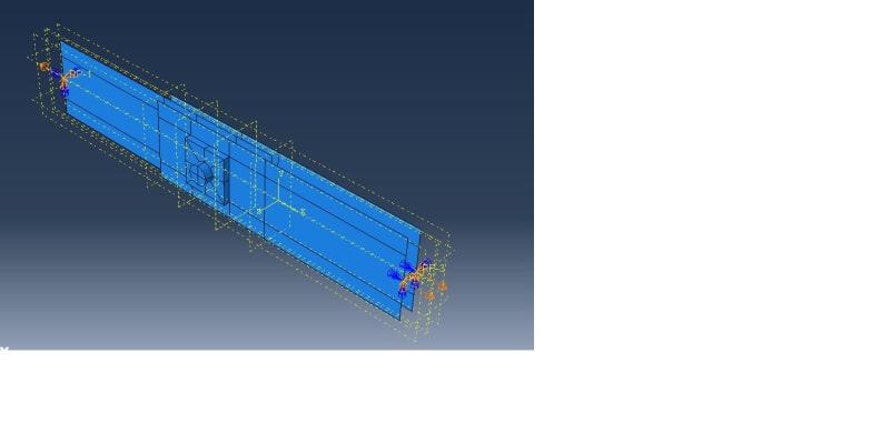
Following the above guidelines, I have modeled the plate, i.e First I created a shell planner model using the rectangular opening following this with solid extrude command I have created the inside rectangular solid block, in the part module in Abaqus. In the property module, I have assigned solid element types for the rectangular block inside and shell element type for the rest of the plate portion.
But while meshing I am not able to select the solid elements separately. I can only select the shell element part, which has been assigned S4R mesh. But I am not able to verify whether the solid element part has been assigned the C3D8R element or not, neither I am able to assign any element type as I am not able to select that part.
The picture of my model is attached in the below link.
[URL unfurl="true"]https://res.cloudinary.com/engineering-com/raw/upload/v1666294353/tips/Plate_with_solid_block_ww2pvr.docx[/url]
Could anyone please advise if my modeling technique is correct and then how I can verify and assign element type for the solid rectangular block?
Many thanks!

