Eng-Tips is the largest engineering community on the Internet

Intelligent Work Forums for Engineering Professionals

  • Congratulations waross on being selected by the Tek-Tips community for having the most helpful posts in the forums last week. Way to Go!

Series connection of FCV and PRV

Status
Not open for further replies.

Kadongo

Mechanical
Feb 22, 2024
9
0
0
SA
Hi All,

Many Thanks for your help,

I need to know what are the considrations to be noted in case of a series connection of flow control valves group and PRV group as per the follow pic:
WhatsApp_Image_2024-03-14_at_12.47.27_da8a0853_lcldaq.jpg


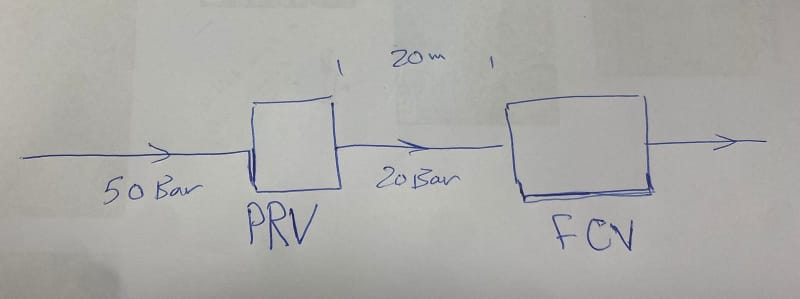
I know that those valves shall fight each other but I am not sure about this? and what is the considreations in tems of hydraulic sizing?

Many thanks
 
Replies continue below

Recommended for you

1503-44 said:
Maybe I'll understand better if you can explain to me how a regulator or any other control valve can modulate as needed to change DP without changing flow. IMO, that is not hydraulically possible.
You have three variables, not two: Flow, Cv, and DP. For any given flow, any possible DP can be generated with the correct Cv.

All right, here we go. A 50 bar reservoir is connected to a distribution header feeding a plurality of users. In between is a regulator set at 20 bar. Lets say four users are currently active. Each takes a constant flow of water (n) via a positive displacement pump. The regulator is whatever % open creates a Cv that gives 30 bar DP at flow (4n). Now the pressure in the reservoir changes instantly to 45 bar. The users are still chugging away. The regulator is still at the same % open, so the Cv is the same, the flow is still (4n), so the DP across the regulator is still 30 bar. Outlet pressure therefore 'instantly' drops to 15 bar. The regulator senses the error of -5 bar at its outlet and starts to open in response. It's slow because someone put a 6 ft long actuator on it for some reason. The valve is slightly more open now, and Cv has increased. Flow is still (4n), but DP has now decreased from 30 bar to 29 bar. The outlet pressure is 16 bar now. Cv creeps higher as the valve keeps opening ever so slowly, DP is now 28 bar. Flow still (4n), outlet pressure is now 17 bar.
This goes on until finally the regulator has caught up and reestablished the set point. Inlet pressure is now 45 bar, outlet pressure is back to 20 bar. Flow is still (2n). DP is now 25 bar. The valve has modulated as needed to change DP without changing flow.

But wait! Lets kick on another user. Flow is now (5n). Our slow valve is only open enough to generate 25 bar DP at (4n), so the DP jumps to 39 bar. Outlet pressure is now a pitiful 6 bar. The slow regulator starts to open again and finally comes to rest at some Cv that gives 20 bar outlet at (5n) flow. With 45 bar inlet, DP is now back to 25 bar and all is right in the world. The valve has modulated as needed to change DP without changing flow.

But wait! The reservoir magically goes back to 50 bar now. The regulator adjusts again, and comes back to some Cv that gives the required 20 bar outlet and 30 bar DP, at (5n) flow. The valve has modulated as needed to change DP without changing flow.

At no point in this excruciatingly long and wordy exercise did the regulator changing position cause a change in flow. The regulator (or a PID controlled actuated valve operating on downstream pressure) reacts to flow changes based on demand when they impact the outlet pressure, sure, but it does not directly change the flow rate (short of maxing out its travel). Replace the PD users above with an FCV that holds a set flow and the scenario is the same as OP's.
 
I have already explained above why your scenario does not compute. When you say instaneous, even if the system is small enough to almost make that assumption, you can not. When you say instaneous, you are saying, Let's ignore all the pressure waves that have to travel from system inlet to outlet and back that must occur in that instant. No matter how small that the time step is between one steady state solution to the next, they must be allowed to happen. You have ignored the dynamics and simply assumed that you can magically switch between two steady state solutions.

You have changed upstream pressure, flow rate remained the same, still the same 30b dP, Cv is still the same, the PI just now gets the message, 15b. But that pressure drop to 15b somehow occurs, even though the downstream pressure at the customer's location is still 20b. How did that 20b of pressure in the entire downstream pipeline just turn into 15b? No change was made to the downstream pressure. The PRV is still 1/2 milisecond before opening. Its sensor is reading 15, but the PI is still transmitting 20. At the sensor we have 15b, but just to the downstream side of the sensor, and all points downstream, flow is still at 4 moving towards the customers and pressure is still 20b. That downstream water now starts backflowing into your 15b. The entire downstream section just reversed flow. Even if just for a 1/2 milisec, that's what just happened. That pressure wave and flow hits the sensor, OMG its water hammer and its a 40b shock wave from the quick collision with the flow from upstream. PI gets that and now wants to close the PRV. That's what happens in your scenario, but it won't because the downstream pressure cannot instaneously go from 20 to 15b. There is a different process working.

The real process, not at all like yours, is one that does not require magical pressure reduction downstream. It propagates from upstream, where changes were made, to the down stream side, through the valve to the system outlet. There it echos back to the PRV without causing reverse flow, just slower flow,

In a long pipeline system these changes are slow and even perceptible to a casual observer. In a small system, they happen so fast it can appear magical, but it is not. A long, or short pipeline makes no difference, other than the time necessary for them to happen. All must occur and they do. It might take 15m minutes in a long pipeline, or just milliseconds in a short one. The time depends on sonic velocity in the fluid and the distances involved.

Do you need me to do the calculations, or simulation?


--Einstein gave the same test to students every year. When asked why he would do something like that, "Because the answers had changed."
 
I have searched You Tube. There is a lot of stuff about how control valves sense out of process condition limit variables, how PID gets the sensor signal and translates that to the correct action for the valves to take to try to regain control, and how the valve responds to position change signals from the PID, but I have not yet found anything about how process condition upsets move through the hydraulics of a system and arrive at the sensors, which is actually what initiates the valve's response in the first place. It looks to be analogous to those that look at a pump curve, and come up with an operating point, then ignore the system curve and expect their pump to provide the right flow rate based on some FCV setting, finally deciding they need a VFD to make it work right.

Looks like I might have to do this kind of a video.

--Einstein gave the same test to students every year. When asked why he would do something like that, "Because the answers had changed."
 
1503-44 said:
When you say instaneous, you are saying, Let's ignore all the pressure waves that have to travel from system inlet to outlet and back that must occur in that instant.
Yes, because they are not relevant to the response behavior of the valve. The propagation of pressure waves at the speed of sound is so much faster than the response of a regulator or control valve that the pressure propagation can be said to be instantaneous.

1503-44 said:
But that pressure drop to 15b somehow occurs, even though the downstream pressure at the customer's location is still 20b.
Why would the downstream still be 20 bar? As soon as the 'pressure wave' as you put it travels through at 1500 m/s or so the downstream of the regulator will be 15 bar. Nothing is holding that 20 bar pressure downstream of the regulator. If you mean downstream of the FCV assembly, when the 'pressure wave' hits the flow element I'm assuming for example purposes is upstream of the FCV, the pressures will go from 20 bar / X bar across the element to 15 bar /(X-5) bar across the element, and the FCV wont even notice. There is no reason for the flow to change.

The whole point of the example is that changing DP across a regulator does not necessarily change the flow. The DP across a variable Cv device can change at constant flow, just as the DP can remain constant when flow changes.
 
OK. Theoretically it could happen, but reality is it cannot. However practically it looks to us like it does. I can't make a simulation of constant flow with constant pressure drop, because when pressure drops, flow rate changes immediately. The Cv of the valve remains constant. Cv cannot change until after the sensor picks up the pressure drop and the controller adjusts the valve lift to get to the new Cv that would keep the flow constant and either overshooting, or closer and closer approximation to the set point are not avoidable, so some differences in flow is always going to be there. But if step changes are small, effects can be reduced to less than one can measure, or care about, so the getting there effects can be ignored. It's the time scale thing.

--Einstein gave the same test to students every year. When asked why he would do something like that, "Because the answers had changed."
 
Have seem a similar system in action, but with the FCV first and PVC second. The PVC was controlling the pressure between the valves. Did not work. The millisecond the PVC moved the pressure in the incompressible water would change and the Flow across the FCV would change and the two valves would hunt.

The solution was to slow down the PCV and run a stepped dead band control. If the Pressure was outside the dead band then step the PCV and wait for the FCV to respond then check the pressure and dead band again.
 
That's a good way to think about it. The early bird gets the worm.

When you slow one of the valves down more than the other you almost deactivate it entirely. If the FCV acts first, the change in flow causes a change in pressure. The PCV won't see P2 until it wakes up and takes action. When it does finally wake up, it will move (if it needs to) to keep pressure within bounds, which changes flow. Then it goes back to sleep. The FCV was watching everything and says, oh no you don't, flow should be here. PCV is sound asleep. The net result is you can remove the PCV.

If you really want flow control AND you do have a critical pressure limit, like KevinNZ needed, then try sending one valve a flow rate signal to position its Cv. Then install a pressure tap and make P_limit an override. Both flow and pressure signals are sent to a hi, or a low relay. The relay selects the the highest signal, if its a hi relay, or the lowest signal, if its a lo relay, and sends that as the output signal to the controller, which sets the valve position. You may still get fighting action, if the set points are incompatible, or gain is too high, but at least the excessive motion will be limited to one valve.

--Einstein gave the same test to students every year. When asked why he would do something like that, "Because the answers had changed."
 
Status
Not open for further replies.
Back
Top